8-104
ELECTRICAL COMPONENTS
EAS30560
CHECKING THE CRANKSHAFT POSITION
SENSOR
1. Disconnect:
• Crankshaft position sensor coupler
(from the wire harness)
2. Check:
• Crankshaft position sensor resistance
Out of specification Replace the crank-
shaft position sensor/stator assembly.
a. Connect the digital circuit tester () to the
crankshaft position sensor coupler as
shown.
b. Measure the crankshaft position sensor
resistance.
EAS30561
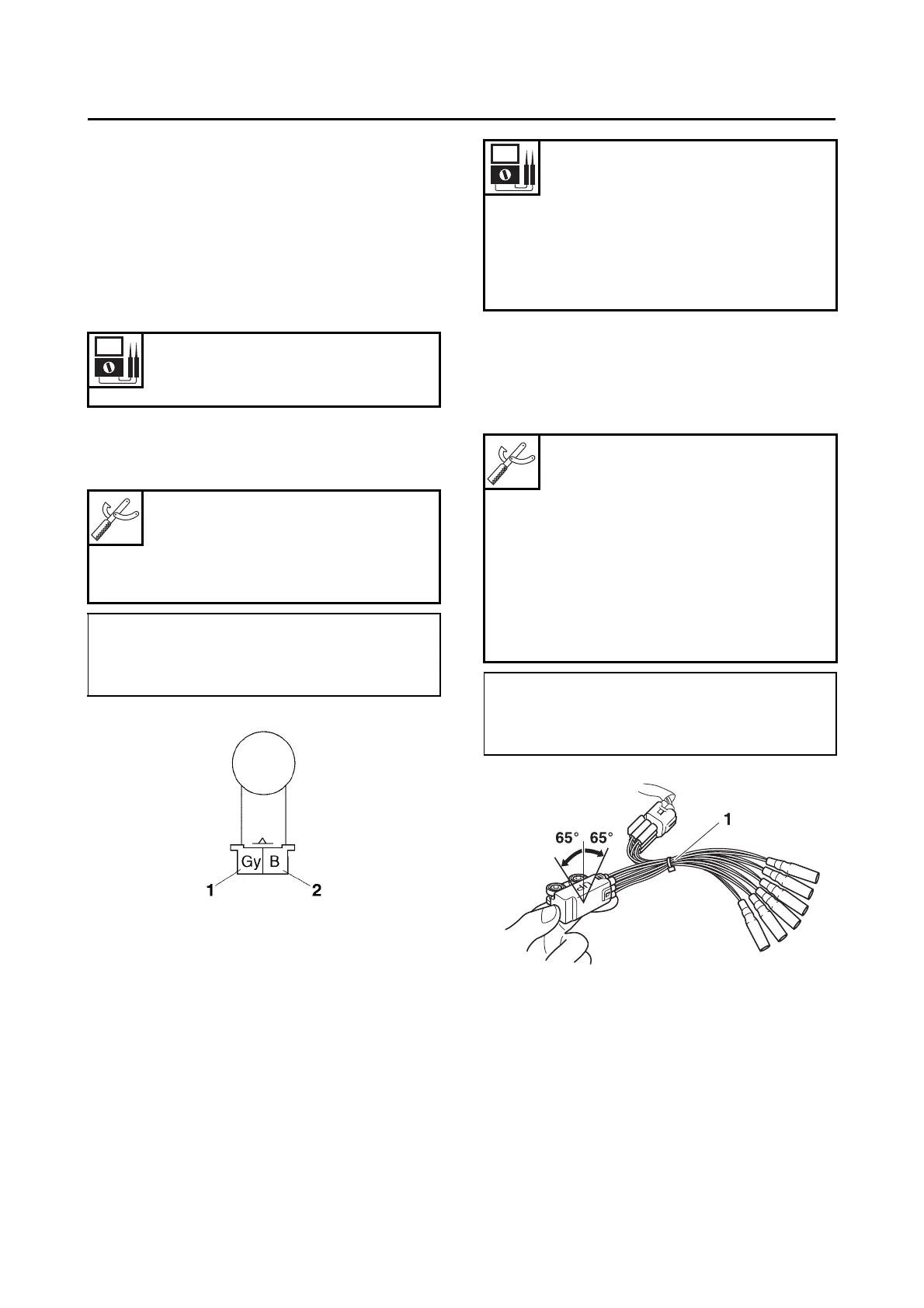
CHECKING THE LEAN ANGLE SENSOR
1. Remove:
• Lean angle sensor
(from the bracket.)
2. Check:
• Lean angle sensor output voltage
Out of specification Replace.
a. Connect the test harness– lean angle sen-
sor (6P) “1” to the lean angle sensor and
wire harness as shown.
b. Connect the digital circuit tester (DC V) to
the test harness– lean angle sensor (6P).
c. Push the ON/start switch.
d. When turn the lean angle sensor to 65.
e. Measure the lean angle sensor output volt-
age.
Crankshaft position sensor
resistance
228–342
Digital circuit tester (CD732)
90890-03243
Model 88 Multimeter with
tachometer
YU-A1927
• Positive tester probe
Gray “1”
• Negative tester probe
Black “2”
Operating angle
65
Output voltage up to operating
angle
0.4–1.4 V
Output voltage over operating
angle
3.7–4.4 V
Digital circuit tester (CD732)
90890-03243
Model 88 Multimeter with
tachometer
YU-A1927
Test harness– lean angle sensor
(6P)
90890-03209
Test harness– lean angle sensor
(6P)
YU-03209
• Positive tester probe
Yellow/Green (wire harness color)
• Negative tester probe
Black/Blue (wire harness color)

 Loading...