8-108
ELECTRICAL COMPONENTS
b. Measure the throttle position sensor maxi-
mum resistance.
3. Install:
• Throttle position sensor
When installing the throttle position sensor,
adjust its angle properly. Refer to “ADJUSTING
THE THROTTLE POSITION SENSOR” on
page 7-13.
EAS30582
CHECKING THE ACCELERATOR POSITION
SENSOR
1. Remove:
• Accelerator position sensor
EWA16700
• Handle the accelerator position sensor with
special care.
• Never subject the accelerator position sen-
sor to strong shocks. If the accelerator po-
sition sensor is dropped, replace it.
2. Check:
• Accelerator position sensor maximum resis-
tance
Out of specification Replace the accelera-
tor position sensor.
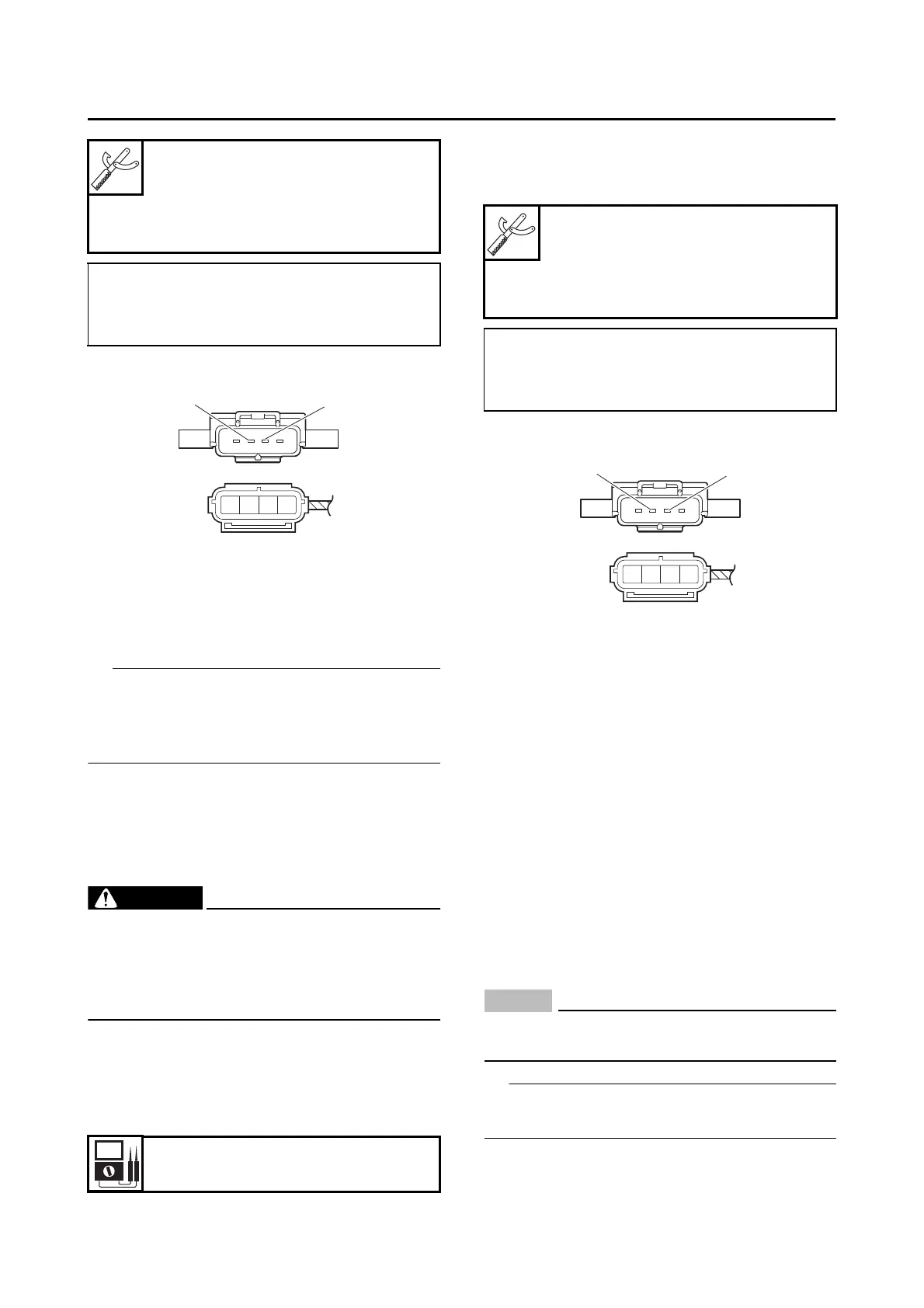
a. Connect the digital circuit tester () to the
accelerator position sensor terminals as
shown.
b. Measure the accelerator position sensor
maximum resistance.
3. Install:
• Accelerator position sensor
EAS30592
CHECKING THE THROTTLE SERVO MOTOR
1. Remove:
• Air filter case
Refer to “GENERAL CHASSIS (3)” on
page 4-17.
2. Check:
• Throttle valve operation
Throttle valves do not fully close
Replace the throttle bodies.
a. Connect two C-size batteries to the throttle
servo motor terminals “1” as shown.
NOTICE
ECA20060
Do not use a 12 V battery to operate the throt-
tle servo motor.
Do not use old batteries to operate the throttle
servo motor.
Digital circuit tester (CD732)
90890-03243
Model 88 Multimeter with
tachometer
YU-A1927
• Positive tester probe
Blue “1”
• Negative tester probe
Black/Blue “2”
Resistance
1.08–2.52 k
Digital circuit tester (CD732)
90890-03243
Model 88 Multimeter with
tachometer
YU-A1927
• Positive tester probe
Blue “1”
• Negative tester probe
Black/Blue “2”

 Loading...