 Loading...
Do you have a question about the Yamaha TMAX 2020 and is the answer not in the manual?
| Displacement | 562cc |
|---|---|
| Bore x Stroke | 70.0 mm x 73.0 mm |
| Compression Ratio | 10.9:1 |
| Fuel System | Fuel Injection |
| Ignition System | TCI |
| Transmission | V-Belt Automatic |
| Rear Suspension | Swingarm |
| Front Brake | Hydraulic dual disc, Ø267 mm |
| Rear Brake | Hydraulic single disc, Ø282 mm |
| Front Tyre | 120/70R15M/C 56H |
| Rear Tyre | 160/60R15M/C 67H |
| Overall Length | 2, 200 mm |
| Overall Width | 765 mm |
| Seat Height | 800 mm |
| Wheelbase | 1, 575 mm |
| Wet Weight | 218 kg |
| Fuel Tank Capacity | 15 litres |
| Engine Type | Liquid-cooled, 4-stroke, DOHC, 4-valve |
| Maximum Torque | 55.7 Nm @ 5, 250 rpm |
| Front Suspension | Telescopic fork |
| Overall Height | 1, 420mm |
Details on vehicle and model identification numbers.
Overview of multi-function display, fuel meter, and coolant temperature meter.
Lists necessary special tools, their part numbers, and reference pages.
Provides dimensions, weight, loading capacity, and model information.
Details engine parameters like combustion cycle, displacement, bore, stroke, and oil specifications.
Covers frame, wheels, tires, brakes, and suspension specifications.
Lists voltage, ignition system, coils, charging system, and battery specifications.
Specifies torque values for engine and chassis components.
Illustrates and describes the proper routing of various wires and cables.
Outlines recommended maintenance checks and adjustments for emissions control and general lubrication.
Explains the procedure for using the YDT to check the vehicle and diagnose malfunctions.
Details the procedure for checking fuel, breather, and overflow hoses for cracks or loose connections.
Provides step-by-step instructions for adjusting valve clearance on a cold engine.
Details the procedure for draining and replacing engine oil and oil filter.
Covers removal, disassembly, checking, assembly, and installation of the front wheel and brake discs.
Details the procedures for removing, disassembling, checking, and installing the rear wheel.
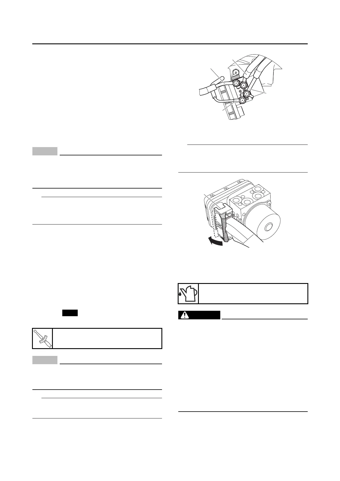
Explains the hydraulic unit assembly removal, checking, installation, and operation test.
Covers handlebar cover removal, checking, installation, and accelerator position sensor adjustment.
Details the removal, disassembly, checking, and installation of front fork legs.
Explains how to remove, check, and install the steering head components.
Covers checking the drive belt and installing the drive belt and drive pulley.
Details handling, disposal, removal, checking, assembly, and installation of the rear shock absorber.
Covers swingarm removal, checking, and installation procedures.
Provides diagrams and charts for the engine oil lubrication system.
Details how to measure compression pressure, including procedure and specifications.
Covers the step-by-step procedure for removing the engine assembly.
Details camshaft removal, checking, installation, and related components.
Explains cylinder head removal, checking, and installation procedures, including warpage measurement.
Covers valve and spring removal, checking, and installation, including valve guide and seat checks.
Details cylinder and piston removal, checking, and installation procedures.
Covers starter motor removal, disassembly, checking, assembly, and installation.
Step-by-step instructions for removing the V-belt case cover and related components.
Details the removal of the V-belt, primary, and secondary sheaves.
Procedures for disassembling the secondary sheave, including spring compressor use.
Explains how to check the V-belt for cracks, damage, wear, and measure its width.
Covers checking the primary sliding sheave and primary fixed sheave for damage.
Details how to check primary sheave weights for cracks or wear and measure their outside diameter.
Steps for cleaning, lubricating, and installing primary sheave components.
Step-by-step guide for installing the primary and secondary sheave assemblies and the V-belt.
Details the procedure for removing the generator rotor and starter clutch assembly.
Steps for removing the stator coil and oil tank assembly.
How to check the starter clutch rollers, idle gears, and contacting surface for wear or damage.
Steps for installing the starter clutch and its bolts, with torque specifications.
Procedures for installing the generator rotor, spacer, and nut.
Details the removal of the clutch assembly, including draining fluids and removing related parts.
Step-by-step instructions for disassembling the clutch, including components like plates, springs, and the clutch boss.
How to check friction plates for damage/wear and measure their thickness.
Instructions on checking clutch plates for damage, warpage, and thickness.
Steps for installing the clutch boss, primary drive gear, clutch boss nut, and tightening.
Procedures for installing clutch weights, thrust plate, springs, plates, and the clutch assembly nut.
How to check the oil pump driven gear, housing, and operation.
Procedure for checking the relief valve body for damage or wear.
Instructions on checking oil pipes for damage and obstructions.
How to check the oil pump drive chain for cracks or stiffness.
Steps for installing the oil pump assembly.
Details the procedure for separating the crankcase halves.
How to check the timing chain for damage and stiffness.
Steps for cleaning mating surfaces and assembling the crankcase halves.
Details the procedure for removing the crankshaft assembly.
Covers the removal of connecting rod caps, rods, and big end bearings.
Procedures for measuring crankshaft runout and checking journal/pin surfaces and bearings.
Steps for lubricating and installing connecting rods, caps, and bearings.
Details the procedure for removing the transmission assembly.
Covers checking transmission gears, movement, and main axle for damage.
Provides diagrams illustrating the cooling system components and their connections.
Covers radiator removal, checking, and installation procedures.
Details oil cooler removal, checking, and installation procedures.
Explains thermostat removal, checking, and installation procedures.
Covers water pump disassembly, checking, assembly, and installation procedures.
Covers fuel tank removal, fuel pump removal, checking, and installation.
Details air filter case removal, throttle body removal, checking, cleaning, and installation.
Covers circuit diagram and troubleshooting for the ignition system.
Details circuit diagram, operation, and troubleshooting for the electric starting system.
Covers circuit diagram, troubleshooting, and checking of the charging system components.
Provides circuit diagram and troubleshooting for the lighting system.
Covers circuit diagram and troubleshooting for the signaling system.
Provides circuit diagram and troubleshooting for the cooling system.
Covers circuit diagram and troubleshooting for the fuel pump system.
Details circuit diagram and troubleshooting for the windshield drive system.
Covers circuit diagram and troubleshooting for the grip warmer system.
Provides circuit diagram and troubleshooting for the seat heater system.
Covers circuit diagram, troubleshooting, emergency mode, and key registration.
Illustrates and lists various electrical components and their locations.
Defines terms used in self-diagnosis, like MIL, DTC, and YDT.
Explains the self-diagnostic function and warning lights.
Describes how warning lights indicate malfunctions and their lighting times.
Information on using the Yamaha Diagnostic Tool (YDT) for malfunction identification.
Lists components connected to the Engine Control Unit (ECU).
Lists components connected to the ABS ECU.
Safety precautions to follow when test riding the vehicle.
Presents the overall ECU and ABS ECU circuit diagrams.
Provides a table of DTCs, symptoms, probable causes, and fail-safe operations.