3-2
Art: 714365-00G Rev. Date: 06-Aug-12
Document Owner: C. Fetters
(609) 454-9304
Rev: 14 Apr 2010
Sample Handling
System
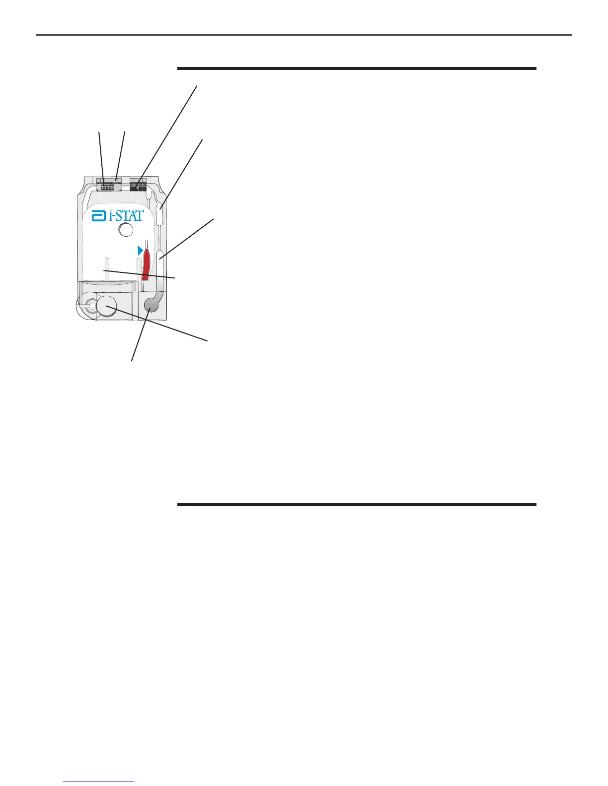
Part Function
Sensor Channel The sensor channel directs the sample from the
sample chamber to the sensors. An extension of this
channel becomes a waste chamber to receive the
calibrant solution as it is displaced by the sample.
Air Chamber An air chamber is located in blood gas/electrolyte/
chemistry/hematocrit cartridges between the sample
chamber and sensor channel. This creates an air
segment between the calibrant solution and the
sample to prevent the two from mixing. The size of
the air segment is monitored by the analyzer.
Sample Chamber The sample chamber includes the sample well and
the channel leading from the well up to the fill mark.
When filled, the sample chamber contains sufficient
sample for testing. Sample volume and placement are
monitored by the analyzer.
Bladder The bladder (concealed by the label) is connected to
the sample well. The analyzer presses on the bladder
to displace calibrant solution from the sensors, to
move the sample from the sample chamber to the
sensors or to mix sample and reagents.
Snap Closure The snap closure creates an airtight seal necessary
for proper fluid movement within the cartridge.
The closure also ensures that calibrant and sample
remain contained within the cartridge during the
testing cycle and subsequent disposal. Immunoassay
cartridges, such as cTnI, use a plastic slide enclosure
clip.
Air Vent An air vent on the underside of the cartridge, beyond
the fluid front, allows the calibrant and the sample to
flow forward, but not out of the cartridge.
Waste Chamber A waste chamber (beneath the cartridge label) holds
calibrant fluid after it has been used.
Sensors
The sensors are electrodes microfabricated on silicon chips. Electrodes have
chemically sensitive coatings such as ion-selective membranes and enzyme
layers. In cartridges that perform coagulation tests, reagents, such as clot
activators, are coated on the plastic above the sensors. Each sensor is connected
to a contact pad by a signal line. The sensors respond to the calibrant
solution and the sample by producing measurable signals related to analyte
concentration. The performance characteristics for each sensor are described
in the Cartridge and Test Information section. The section on theory describes
the measurement principles.
Contact Pads
The contact pads conduct the signals generated by the sensors to the analyzer.
In order to function properly, care must be exercised not to contaminate the
contact pads during cartridge handling.
Heating Elements
All i-STAT cartridges require thermal control at 37°C, and include heating
elements on the underside of the sensor chips which are contacted and heated
by the handheld's thermal probes.
Sample Well
Sensors
Contact
Pads
 Loading...