4 PKE-SWD-32, interface for motor-starter combination with PKE PKE12/32
4.3 Engineering
SmartWire-DT module IP20 01/20 MN05006001Z-EN www.eaton.com 99
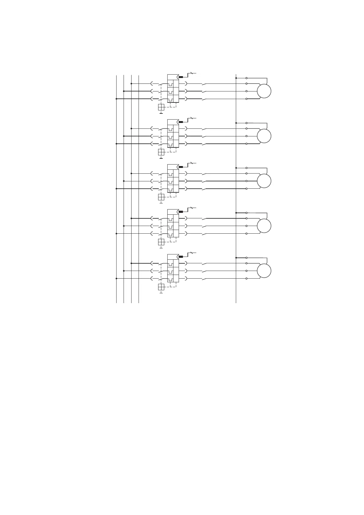
Figure 47: Main circuit for safety-related disconnection of drive groups
In an emergency, the power for the contactor coils can be switched off using
the enable circuit of the safety relay. By using additional SmartWire-DT
Power modules, contactor groups are made that can be switched off
together in an emergency. With this circuitry, controls can be assembled up
to Safety Category 1 to EN 954-1. The safety relay must comply with Cate-
gory 1 or higher (e.g. ESR5-NO-41-24VAC-DC) in this example.
4.3.4 Feedback loop
The auxiliary contact integrated in the contactor is a mirror contact according
to IEC/EC 60947-4-1. Using this contact the state of the main contacts can be
reliably signalled. The mirror contact can be included into the feedback circuit
of the safety relay so that the safety relay only gives a new enable signal
when the contactor is open.
PE
L1
L2
PE
L3
-M1
3~
M
UV
WPE
UV
W
PE
-Q1
1
3
5
I>
I>
I>
2
4
6
-M1
-Q11
1
35
24
6
-M1
3~
M
UV
WPE
UV
W
PE
-Q2
1
3
5
I>
I>
I>
2
4
6
-M2
-Q12
1
35
24
6
-M1
3~
M
UV
WPE
UV
W
PE
-Q3
1
3
5
I>
I>
I>
2
4
6
-M3
-Q13
1
35
24
6
-M1
3~
M
UV
WPE
UV
W
PE
-Q4
1
3
5
I>
I>
I>
2
4
6
-M4
-Q14
1
35
24
6
-M1
3~
M
UV
WPE
UV
W
PE
-Q5
1
3
5
I>
I>
I>
2
4
6
-M5
-Q15
1
35
24
6
10 10 10 10 10

 Loading...


