7 Pilot devices M22-SWD…
7.2 M22-SWD front mount
SmartWire-DT module IP20 01/20 MN05006001Z-EN www.eaton.com 161
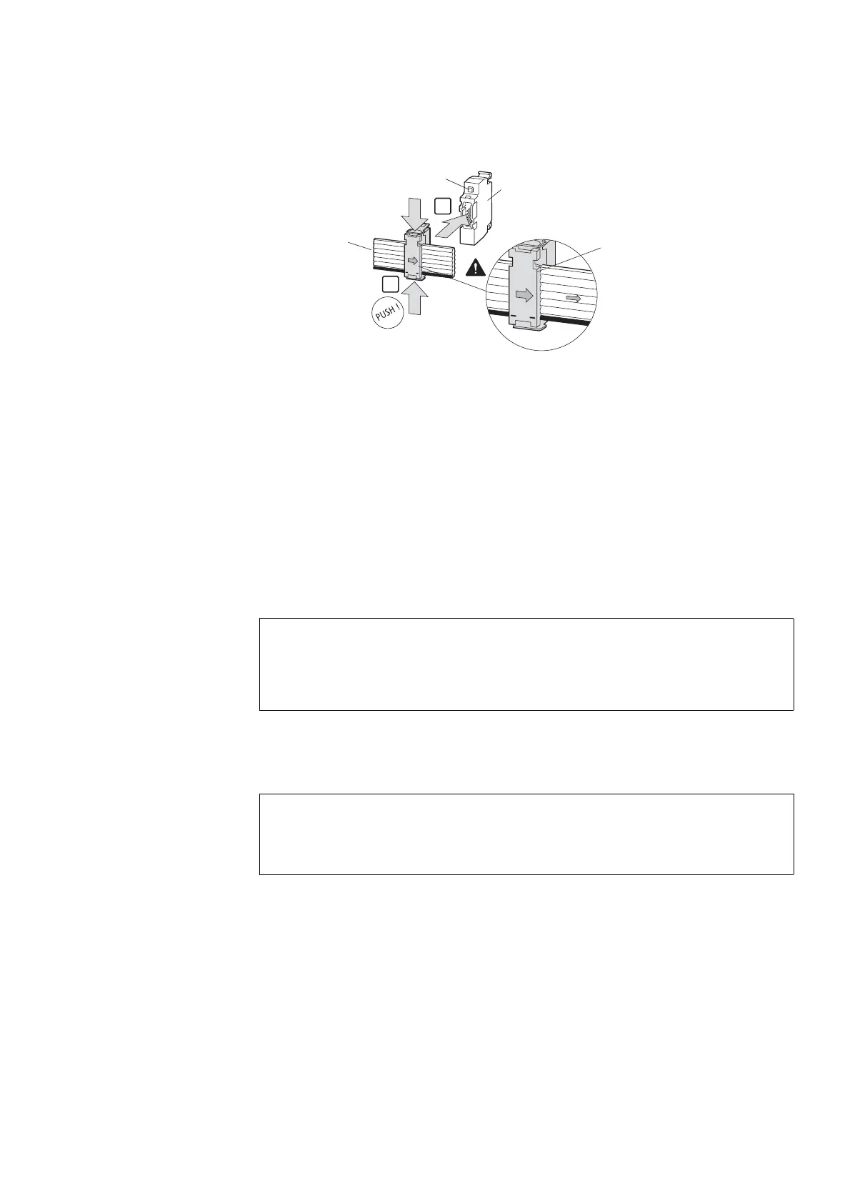
Figure 62: Connection of the function element to the SWD ribbon cable
a Diagnosis LED
7.2.4 Commissioning
The automatic addressing of all modules in the SmartWire-DT network is per-
formed via the gateway (actuation of the configuration pushbutton on the
gateway) during commissioning. During the addressing process the Smart-
Wire-DT diagnosis LED on the rear side of the M22-SWD front function ele-
ment flashes. Once the addressing process is completed, the LED indicates
a green continuous light.
7.2.5 Exchange of modules
After replacement of the modules and connection of the voltage the configu-
ration button must be pressed. When this is done, the new module will be
assigned an address.
1
2
SWD4-8SF2
SW
D4-8S
F
2
S
W
D
4
-8SF2
-
5
+
1
5
V
SWD4-8SF2-5
+
1
5V
SWD4-8SF2-5
M22-SWD-K...
M22-SWD-LED...
M22-SWD-NOP
M22-SWD-R
SWD4-100LF8-24
SWD4-3LF8-24-2S
SWD4-5LF8-24-2S
SWD4-10LF8-24S
①
ACHTUNG
Replacement of the SmartWire-DT function elements is not per-
mitted until the entire SmartWire-DT system has been switched
off.
ACHTUNG
The order of the SmartWire-DT units must not be altered.

 Loading...


