2 I/O modules EU5E-SWD…
2.10 Digital module EU5E-SWD-4D2R
42 SmartWire-DT module IP20 01/20 MN05006001Z-EN www.eaton.com
2.10 Digital module EU5E-SWD-4D2R
2.10.1 INTRODUCTION
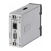
The SmartWire-DT I/O module EU5E-SWD-4D2R provides four digital inputs
and two digital relay outputs.
Diverse sensors can be integrated via the four inputs.
Both digital relay outputs Q0 and Q1 can be used in the actuation of actua-
tors up to a rated operational current of 3 A, AC-15 at 250 V.
The inputs'/outputs' status is indicated with the help of LEDs.
The SmartWire-DT diagnostic LED indicates the network status.
2.10.2 Surface mounting
Figure 16: Connections of the modules EU5E-SWD-4D2R
2.10.3 Engineering
Module EU5E-SWD-4D2R can be used for directly actuating AC or DC con-
tactors with larger pull-in power. The relay outputs must be fuse-protected
against overload and short-circuits.
a SmartWire-DT cable with external device plug
b SmartWire-DT diagnostics LED
c Status LEDs of the inputs and outputs
d I0 – I3 (inputs)
e Q0, Q1 (outputs)
f 0-V connection

 Loading...


