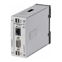
5 Connection PKE-SWD for motor-protective circuit-breaker PKE12/32/65
5.2 Surface mounting
124 SmartWire-DT module IP20 01/20 MN05006001Z-EN www.eaton.com
5.2 Surface mounting
Figure 55: Figure 1: Connections PKE-SWD
a Connection of SmartWire-DT external device plug
b Diagnostics LED
c Engagement hook for connecting to PKE basic device
d Data interface for PKE control option “Advanced”
The SmartWire-DT external device plug with an adapted SmartWire-DT con-
necting cable is connected to the module PKE-SWD via connection 1.
Diagnostic LED ② indicates the module’s communication status through the
SmartWire-DT system and the communication state to the PKE trip block
(→ Section 5.7, „Device status“, page 128).
The PKE-SWD is fixed to the corresponding basic devices PKE with the
engagement hook ③. This must be operated before the PKE-SWD is
removed. When installing the PKE-SWD, the PKE basic device must not be
fitted with a PKE trip block.
PKE-SWD and PKE trip block communicate through the data interface ④.
5.3 Engineering
The PKE-SWD can be combined with motor-protective circuit-breakers
PKE12, PKE32 and PKE65. The trip blocks used that can be combined with
the PKE basic devices must be of type XTUA or PKE-XTUWA. For each PKE-
SWD one motor-protective circuit-breaker PKE with PKE trip block can be
connected.
The following trip blocks of the type “Advanced” can be combined with the
two PKE basic devices PKE12, PKE32 and PKE65.
→
For detailed instructions on how to connect the SmartWire-DT
external device plug (SWD4-8SF2-5) to the 8-pin SmartWire-DT
ribbon cable, refer to the "Mount the external device plug" sec-
tion in manual MN05006002Z-EN (previously AWB2723-
1617en).

 Loading...


