8 SL4-SWD and SL7-SWD base modules for signal towers
8.4 Installation
206 SmartWire-DT module IP20 01/20 MN05006001Z-EN www.eaton.com
8.4 Installation
The SmartWire-DT base modules are designed for screw fixing. They can be
placed in any mounting position.
8.4.1 Mounting
For ease of wiring, leave a clearance of at least 3 cm to the wall or adjacent
devices.
To mount the SmartWire-DT base module, follow the steps below:
▶ At the spot where you want to mount the module, make an opening that
is large enough for the SWD ribbon cables to go through. The ribbon
cables have a width of 19 mm. The rapid mounting adapter's opening has
a diameter of 33 mm.
▶ Drill 4 holes for the rapid mounting adapter using the mount drilling tem-
plate found in installation instructions IL047002ZU.
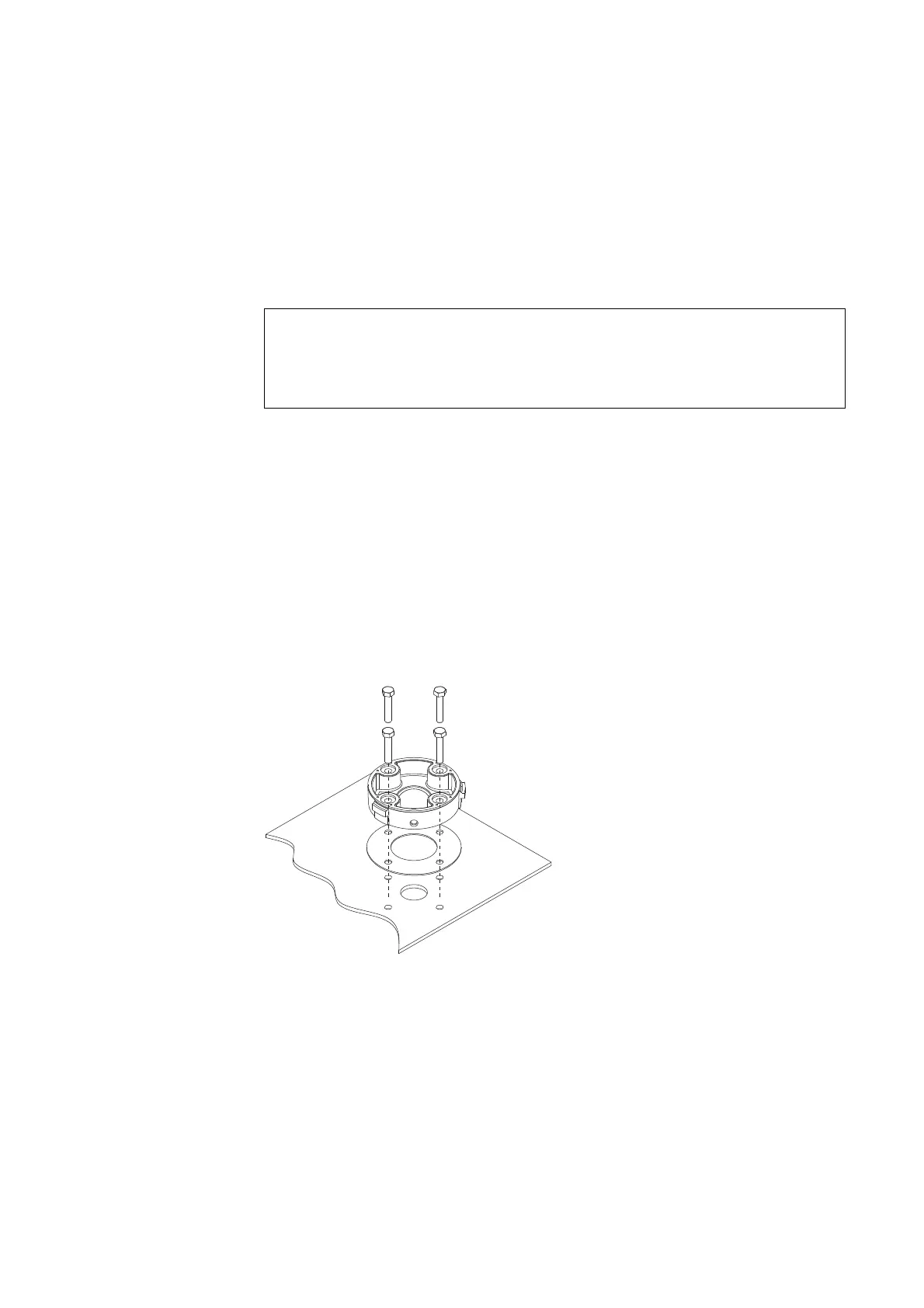
▶ Use the M5 screws to fasten the rapid mounting adapter to the equip-
ment.
Figure 71: Installing the rapid mounting adapter
▶ Thread the ribbon cable coming from the SmartWire-DT coordinator, as
well as the ribbon cable starting from the base module, through the rapid
mounting adapter's opening.
▶ If necessary, connect an external auxiliary power, → Section
8.4.2, „Connecting the external supply voltage“, page 208.
▶ Connect the SmartWire DT→ Section 8.4.3, „Connect SmartWire-DT“,
page 208.
ACHTUNG
The specified IP66 degree of protection will only be achieved on
a smooth, solid surface with the same degree of protection, and
only if a signal tower is installed.
1 Nm
(10 lb-in.)
4 x M5

 Loading...


