3 Switching on DIL-SWD-32-001, DIL-SWD-32-002 contactors
3.2 Surface mounting
66 SmartWire-DT module IP20 01/20 MN05006001Z-EN www.eaton.com
3.2 Surface mounting
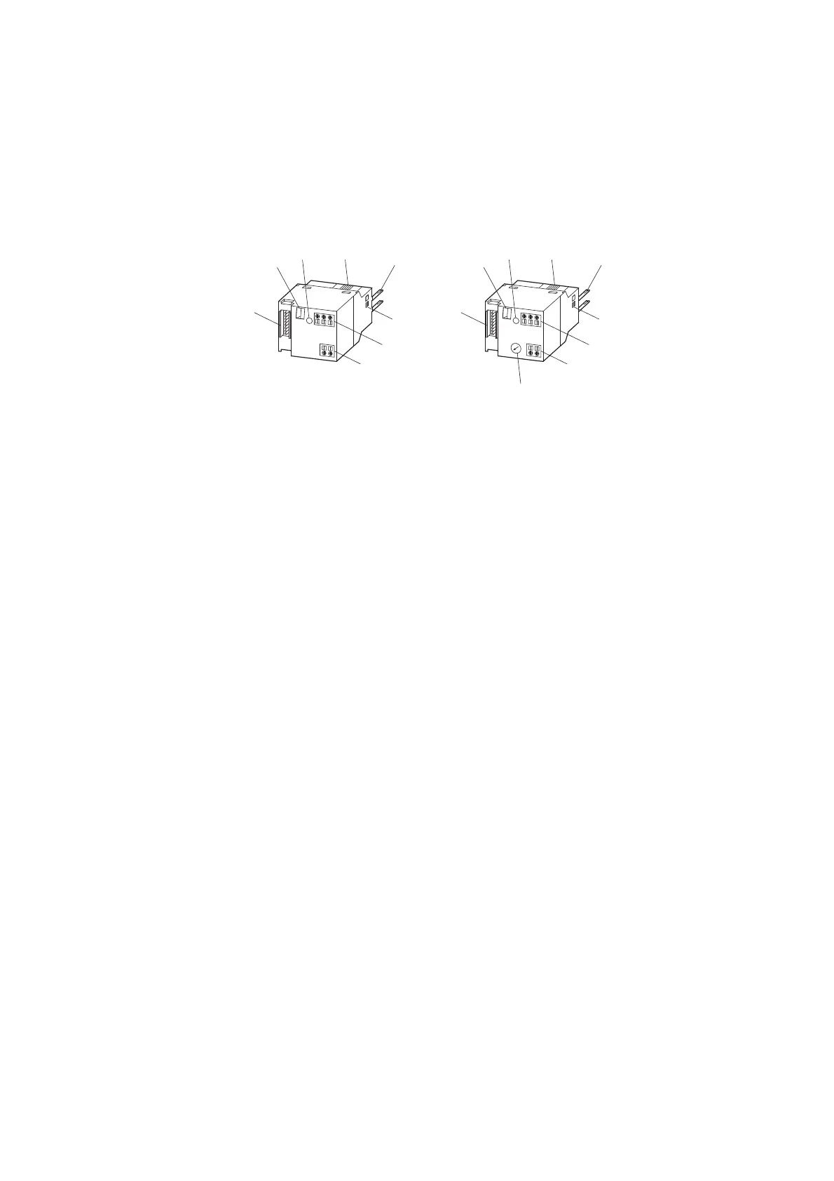
The following diagram shows the two modules.
The external device plug with an adapted SmartWire-DT connecting cable is
connected to the contactor module DIL-SWD via connection ① .
The communication status and switching command via the SmartWire-DT
system are indicated by way of a two-color diagnostics LED ③
(→ Chapter 3 “Switching on DIL-SWD-32-001, DIL-SWD-32-002 contac-
tors”, page 81).
As well as the communication signals a 24 V DC supply for the contactor coil
is also transmitted via the SmartWire-DT connection cable. The integrated
electronics transfers the voltage to the connection pins ⑤ that are con-
nected to the contactor coils.
The SmartWire-DT module for DILM is connected with the contact bridge of
the contactor with the catch slider ④. Feedback on the switching status of
the contactor is goes into the field bus.
In addition the status of the connected contactor can be acquired via the
switch position indicator ②.
DIL-SWD-32-001 DIL-SWD-32-002
Figure 26: Structure of the SmartWire-DT modules DIL-SWD-32-001 and DIL-SWD-32-002 for
DILM
a Connection of SmartWire-DT external device plug
b Mechanical switching position indicator
c Diagnostics LED
d Catch slider
e Connection pins
f Adjusting slide for contactor size
g Terminal X0-X1-X2
h Terminal, electrical enable X3-X4
i Selector switch 1-0-A
→
For detailed instructions on how to connect the SmartWire-DT
external device plug (SWD4-8SF2-5) to the 8-pin SmartWire-DT
ribbon cable, refer to the "Mount the external device plug" sec-
tion in manual MN05006002Z-EN (previously AWB2723-
1617en).

 Loading...


