9 Interface module MCB-HK-SWD for circuit-breakers and residual current circuit-breakers
9.5 Commissioning
216 SmartWire-DT module IP20 01/20 MN05006001Z-EN www.eaton.com
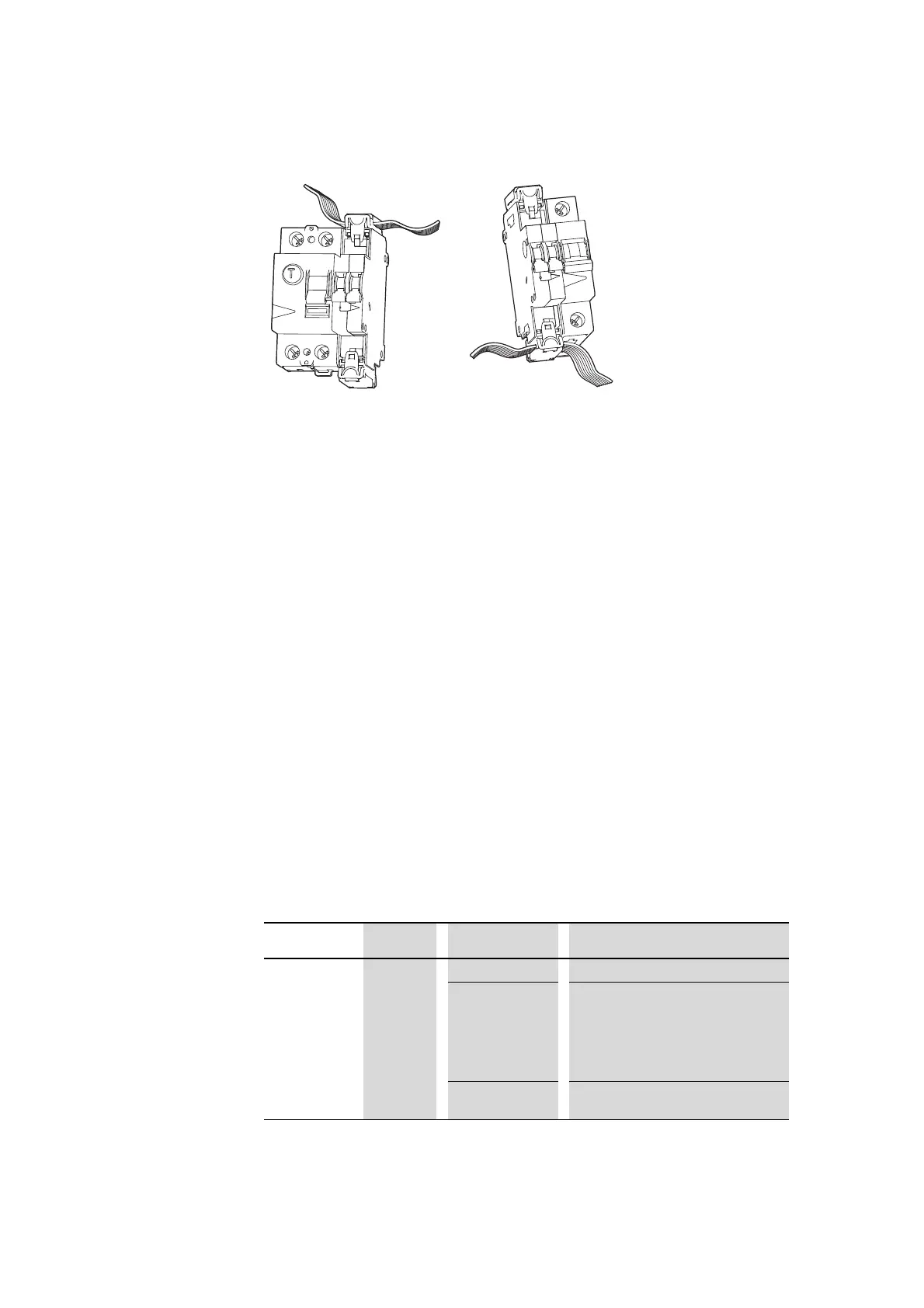
Figure 79: Connecting the SmartWire-DT cable
9.5 Commissioning
During address assignment, the modules’ SmartWire-DT diagnostics LED
flashes. After address assignment, the LED is continuous lit green.
9.6 Exchange of modules
Whenever you replace a module, you will need to press the configuration
button after replacing the module and switching on the voltage. When this is
done, the new module will be assigned an address.
9.7 Device Status
The individual SmartWire-DT modules indicate their device status with the
aid of a diagnosis LED.
Table 60: Diagnostic messages of the SmartWire-DT status LED
→
For detailed instructions for adapting the SmartWire-DT external
device plug (SWD4-8SF2-5) to the 8-pole SmartWire-DT cable,
see chapter "Mount the external device plug“ of manual “Smart-
Wire-DT, The System” (MN05006002Z-EN, previously
AWB2723-1617en).
Designation Color State Message
SmartWire-DT Green Continuous light Device is operating fault-free.
flashing (1 Hz) • addressing process in progress
• after gateway power On
• after actuation of the configuration
button on the gateway
• Module not in current configuration
• invalid type
flashing (3 Hz) Device reports a diagnostics.
(→ Section 9.8.2, "Diagnostics", page 217)

 Loading...


