2 I/O modules EU5E-SWD…
2.7 Digital module EU5E-SWD-4DX
SmartWire-DT module IP20 01/20 MN05006001Z-EN www.eaton.com 29
2.7 Digital module EU5E-SWD-4DX
2.7.1 INTRODUCTION
SmartWire-DT I/O module EU5E-SWD-4DX provides four digital inputs I0 to
I3. The inputs are three-wire digital inputs, and the module also includes the
24 V supply for them.
The inputs' status is indicated with the help of LEDs.
The SmartWire-DT diagnostic LED is used to signal the network's/module's
status.
2.7.2 Surface mounting
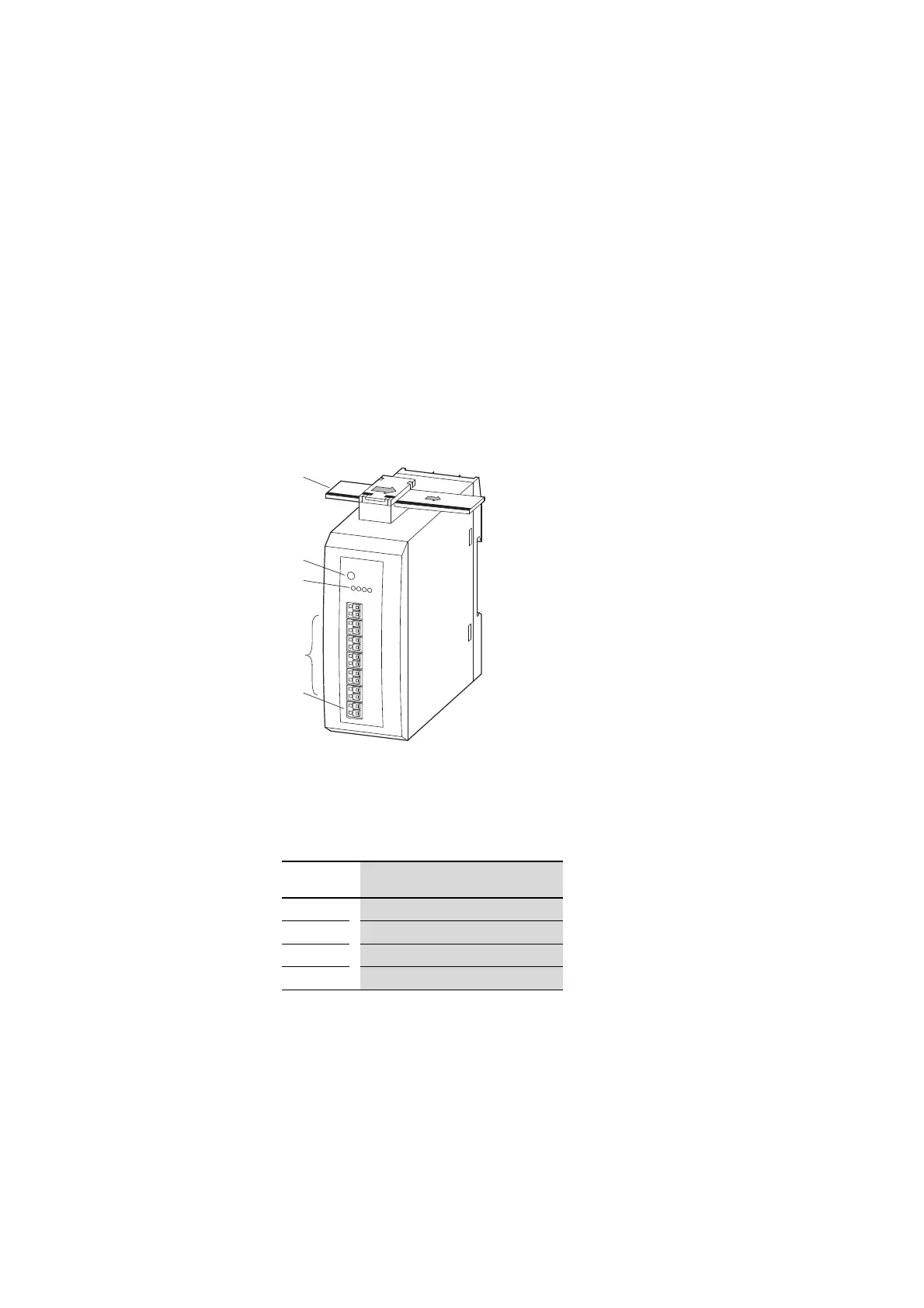
Figure 10: Layout of module EU5E-SWD-4DX
2.7.3 Engineering
The four inputs use a three-wire connection configuration.
A 24 V supply voltage is available for each input. The maximum current draw
for each input is 0.5 A. The supply is short-circuit proof.
On short circuit the SmartWire-DT diagnostics LED flashes and the diagnos-
tic bit is set in the user program. When the short circuit is removed, the sup-
ply voltage is automatically applied again.
a
b
c
d
e
a SmartWire-DT cable with external device plug
b SmartWire-DT diagnostics LED
c Status LEDs of the inputs
d I0 – I3 , (I, I+, I-)-inputs
e 0-V-24-V connection
Input Description
I
x
Input signal I
x
I
x
- 0-V-supply voltage input I
x
I
x
+ 24-V-supply voltage input I
x
x 0, 1, 2, 3

 Loading...


