10 SmartWire-DT universal module M22-SWD-NOP and M22-SWD-NOP-C
10.5 Commissioning
SmartWire-DT module IP20 01/20 MN05006001Z-EN www.eaton.com 223
10.4.2 Base mounting
Universal module M22-SWD-NOPC is fitted to circuit card M22-SWD-I...-
LP… in surface mounting enclosure M22-I….
To do so, proceed as follows:
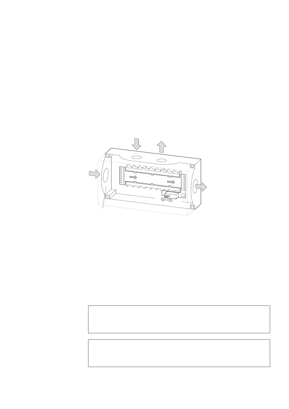
▶ Insert the printed circuit board into the surface mounting enclosure.
Ensure that the PCB is pointing in the correct direction. The direction of
the arrow defines the arrangement of the modules. (the gateway is to the
left of the IN code.)
▶ Equip the slots with the M22-SWD-NOPC universal module. Ensure that
the mounting position is correct (status LED must be at the top). Equip
unused slots with the link M22-SWD-SEL8-10.
Figure 84: Universal module M22-SWD-NOPC in enclosure M22-I3
10.5 Commissioning
The automatic addressing of all modules in the SmartWire-DT network is per-
formed via the gateway during commissioning. Press the configuration but-
ton on the gateway.
During address assignment, the SmartWire-DT diagnostic LED at the back of
the M22-SWD universal module will flash. Once the addressing process is
completed, the LED indicates a green continuous light.
10.5.1 Exchange of modules
1
3
2
1
3
2
1
3
2
IN
OUT
OFF
ON
ON
OFF
M22-SWD4-SF8-20
M22-SWD4-SM8-20
M22-I…
ATTENTION
Switch off the entire SmartWire-DT system before replacing
SmartWire-DT universal modules.
ATTENTION
The order of the SmartWire-DT units must not be altered.

 Loading...


