3 Switching on DIL-SWD-32-001, DIL-SWD-32-002 contactors
3.8 Programming
82 SmartWire-DT module IP20 01/20 MN05006001Z-EN www.eaton.com
3.7.1 Parameterization
Depending on the coordinator being used, the module's parameters will
need to be configured in the programming system or in the SWD-Assist plan-
ning and commissioning program.
3.7.2 Fieldbus-specific characteristics
Field bus Ethercat
Please note the general information for configuring parameters
→ Chapter 12 “Using SWD modules with the EtherCAT field bus”, page
247.
3.8 Programming
3.8.1 DIL-SWD-32-001
The function element has one input byte and one output byte at its disposal.
3.8.1.1 Input points
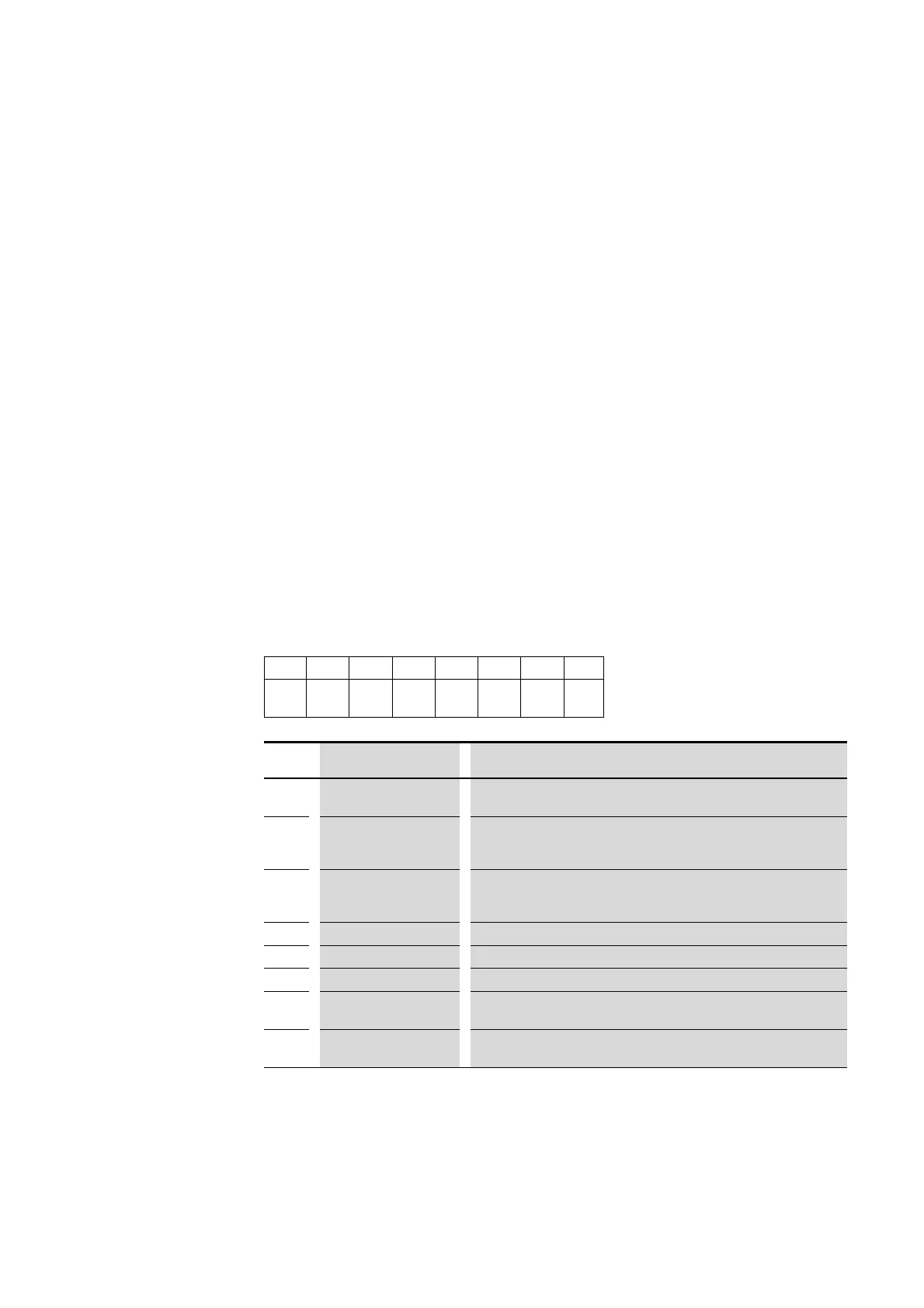
Byte 0:
3.8.1.2 Outputs
Byte 0:
76543210
SUBST PRSNT – DIAG – I1 (X1-
X0)
I0 (X1-
X2)
C
Bit
Designation Description
0 C = Contactor 0: contactor not tripped
1: contactor tripped
1
I0 (X1-X2) 0: Auxiliary contact for X1-X2 opened
1: Auxiliary contact for X1-X2 closed
The meaning depends on the auxiliary switch used.
2
I1 (X1-X0) 0: Auxiliary contact for X1-X0 opened
1: Auxiliary contact for X1-X0 closed
The meaning depends on the auxiliary switch used.
3
Not used –
4
DIAG 0: no diagnostic alarm
5
Not used –
6
PRSNT 0: Module not available
1: Module available
7
SUBST 0: Configured module present
1: Universal module M22-SWD-NOP(C) present

 Loading...


