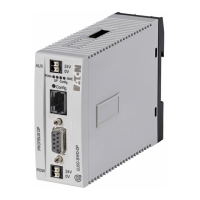
2 I/O modules EU5E-SWD…
2.14 Analog modules EU5E-SWD-4PT and EU5E-SWD-4PT-2
SmartWire-DT module IP20 01/20 MN05006001Z-EN www.eaton.com 61
2.14.6 Fieldbus-specific characteristics
Field bus CANopen
The module is parameterized with the control configurator using the card’s
two associated parameter bytes.
Select the desired model, and the reading representation and refresh rate.
Unused temperature channels must remain set to “unused” according to the
table.
Structure of parameter byte 1:
Structure of parameter byte 2:
Bit Function Configuration
0, 1 Sensor selection
Input 1
Bit 1
0
0
1
1
Bit 0
0
1
0
1
= not used
= PT100
= PT1000
= NI1000
2, 3
Sensor selection
Input 2
Bit 3
0
0
1
1
Bit 2
0
1
0
1
= not used
= PT100
= PT1000
= NI1000
4, 5
Sensor selection
Input 3
Bit 5
0
0
1
1
Bit 4
0
1
0
1
= not used
= PT100
= PT1000
= NI1000
6, 7
Sensor selection
Input 4
Bit 7
0
0
1
1
Bit 6
0
1
0
1
= not used
= PT100
= PT1000
= NI1000
Bold values indicate the default settings.
Bit
Function Configuration
0, 1 Measurement display Bit 1
0
0
1
Bit 0
0
1
0
= degrees Celsius
= degrees Fahrenheit
= Binary value
2, 3
Reading refresh rate Bit 3
0
0
1
1
Bit 2
0
1
0
1
= 0.25 s
= 1 s
= 2.5 s
= 10 s
4
reserved 0
5
reserved 0
6 reserved 0
7 reserved 0
Bold values indicate the default settings.

 Loading...


