7 Pilot devices M22-SWD…
7.3 M22-SWD base fixing
SmartWire-DT module IP20 01/20 MN05006001Z-EN www.eaton.com 189
7.3 M22-SWD base fixing
M22-SWD base function elements are used in connection with M22-I... sur-
face mounting enclosures and M22 front elements.
7.3.1 Surface mounting
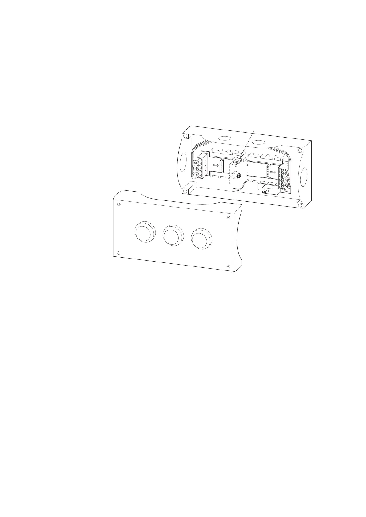
Figure 63: Base function element on a PCB in an M22-I... surface mounting enclosure
a Diagnosis LED
7.3.2 Engineering
The SmartWire-DT base function elements are used in surface mounting
enclosures M22-I1 to M22-I6 with the corresponding M22-SWD-I1-LP1 to
M22-SWD-I6-LP6 PCBs.
Up to six operator control and indicator light functions can be realized with
them. The PCB establishes the connection to the SmartWire-DT network.
The M22 front elements for the control circuit function are used at the front
of the enclosure.
The surface mounting enclosures are connected to the SmartWire-DT net-
work via the SmartWire-DT round cable SWD4 50LR8-24.
The round cable can be connected directly by means of VM20 (metric cable
gland) or plugged in.
8 pole enclosure bushings as plug/socket versions are used for the plug-in
version.
1
3
2
1
3
2
1
3
2
IN
OUT
OFF
ON
①
→
The base function elements replace the previous M22-KC10 /
KC01 contact elements and the corresponding M22 LEDC... ele-
ments. .

 Loading...


