5 Connection PKE-SWD for motor-protective circuit-breaker PKE12/32/65
5.6 Exchange of modules
128 SmartWire-DT module IP20 01/20 MN05006001Z-EN www.eaton.com
5.6 Exchange of modules
After replacement of the modules and connection of the voltage the configu-
ration button must be pressed. When this is done, the new module will be
assigned an address.
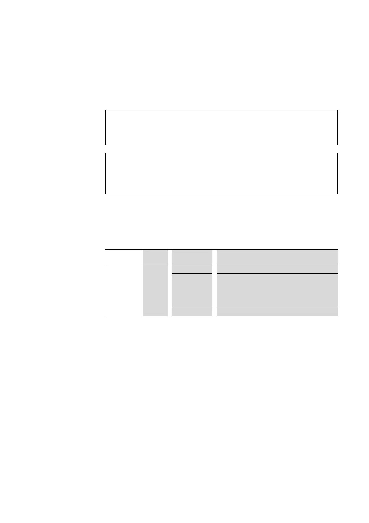
5.7 Device status
The individual SmartWire-DT modules indicate their device status with the
aid of a diagnosis LED. The diagnostics LED can have the following states:
Table 17: Diagnostic messages of the SmartWire-DT status LED
5.8 Parameterization
Depending on the coordinator being used, the module's parameters will
need to be configured in the programming system or in the SWD-Assist plan-
ning and commissioning program.
5.9 Fieldbus-specific characteristics
Field bus Ethercat
Please note the general information for configuring parameters → Section
12, „Using SWD modules with the EtherCAT field bus“, page 247.
ATTENTION
The order of the SmartWire-DT units must not be altered.
DANGER
The exchange of the motor starter or contactor must only be
carried out after the complete system SmartWire-DT is
switched off.
Designation Color State Message
Ready Green Continuous light Device is operating error-free.
Flashing (1 Hz) • Addressing process in progress
• after gateway power On
• after actuation of the configuration button on the gateway
• Module not in current configuration
• invalid type
Flashing (3 Hz) • Communication to trip block PKE is interrupted

 Loading...


