2 I/O modules EU5E-SWD…
2.5 Installation
SmartWire-DT module IP20 01/20 MN05006001Z-EN www.eaton.com 23
2.5 Installation
The SmartWire-DT input/output modules are envisaged for top hat mounting.
They must be installed in a vertical position.
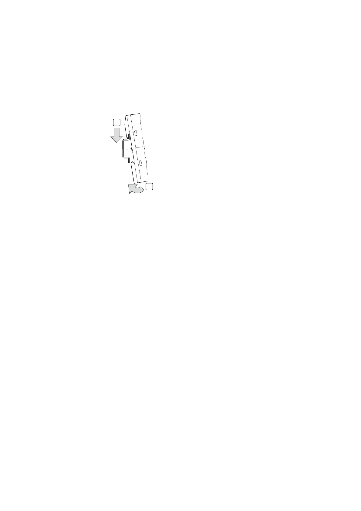
▶ Mount the module on the top hat rail.
Figure 6: Mounting on top-hat rail
▶ Connect the 8-pole SmartWire-DT cable to the SmartWire-DT socket on
the device top.
2.5.1 Connecting signal and supply cables
▶ Connect the inputs/outputs and, if applicable, the supply cables to the
push-in terminals,
▶ observing the permissible cable cross-sections.
2.5.2 Terminal capacities
• flexible: cross-section 0.25 mm² to 1.5 mm², with the ferrule (minimum
length 8 mm)
• solid: 0.25 to 1.5 mm²
• AWG24 to AWG16
2.5.3 Wiring of analog sensors/actuators
▶ Only use shielded cables for connection.
▶ Route the cables separately from power leads or signal cables that carry
differential voltages.
▶ Depending on the prevailing electromagnetic environment, one or both
ends of the shielding should be earthed.
▶ Connect the shielding with the module’s 0 V supply.
→
Detailed instructions explaining how to assemble an SWD4-
8SF2-5 SmartWire-DT external device plug onto an 8-pin Smart-
Wire-DT ribbon cable can be found in the "SmartWire-DT, The
System" manual, in the "Mount the external device plug" sec-
tion.
1
2

 Loading...


