7 Pilot devices M22-SWD…
7.3 M22-SWD base fixing
194 SmartWire-DT module IP20 01/20 MN05006001Z-EN www.eaton.com
7.3.3 Installation
The functional elements are mounted on the PCB M22-SWD-I...-LP… in the
surface mounting enclosure M22-I….
To do so, proceed as follows:
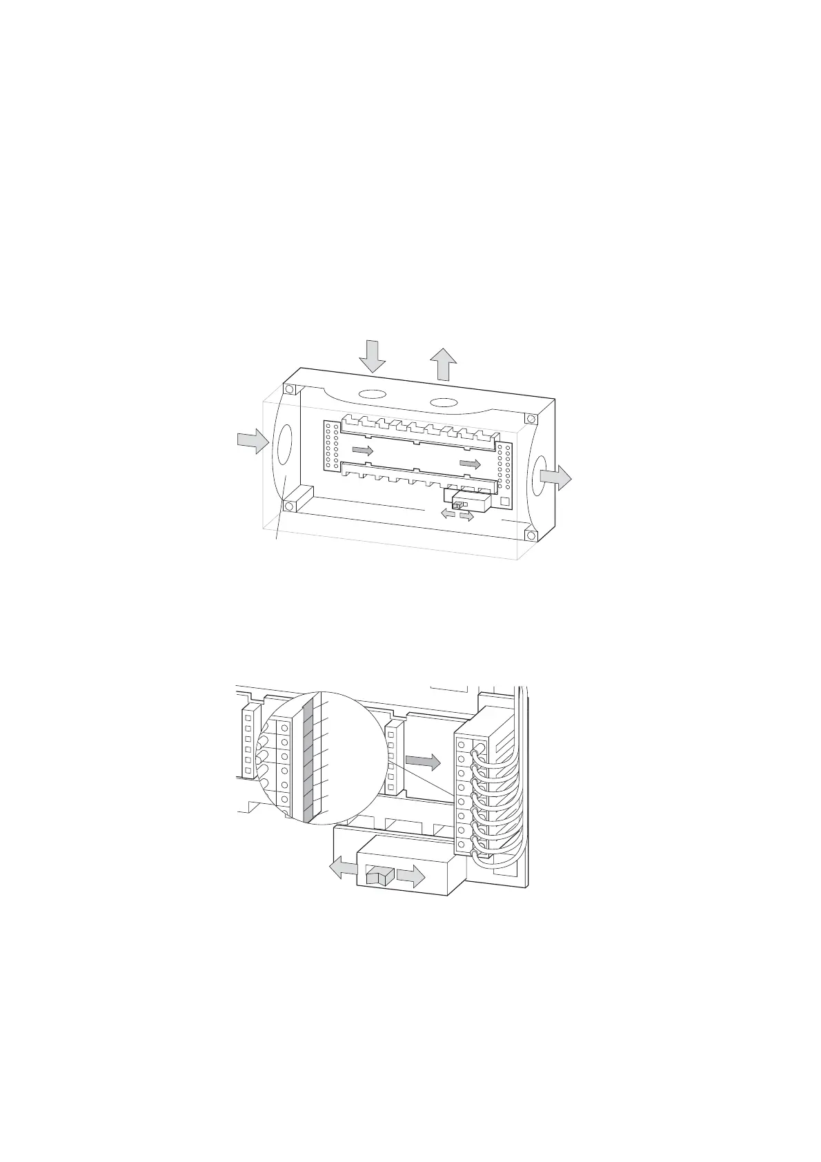
▶ Insert the printed circuit board into the surface mounting enclosure.
Ensure that the PCB is pointing in the correct direction. The direction of
the arrow defines the arrangement of the modules. (the gateway is to the
left of the IN code.)
Figure 66: Surface-mounting enclosure with PCB M22-SWD-I...-LP…
▶ Fix the SmartWire-DT cables to the PCB terminals. Ensure that the color
assignment is correct.
▶ If this is the last SmartWire-DT module, please switch on the terminating
resistor.
Figure 67: Bus termination resistor
▶ Equip the slots with the M22-SWD…C… function elements. Ensure that
the mounting position is correct (status LED must be at the top). Unused
slots must be equipped with the bridge M22-SWD-SEL8 10.
1
3
2
1
3
2
1
3
2
IN
OUT
OFF
ON
ON
OFF
M22-SWD4-SF8-20
M22-SWD4-SM8-20
M22-I…

 Loading...


