3 Switching on DIL-SWD-32-001, DIL-SWD-32-002 contactors
3.3 Engineering
70 SmartWire-DT module IP20 01/20 MN05006001Z-EN www.eaton.com
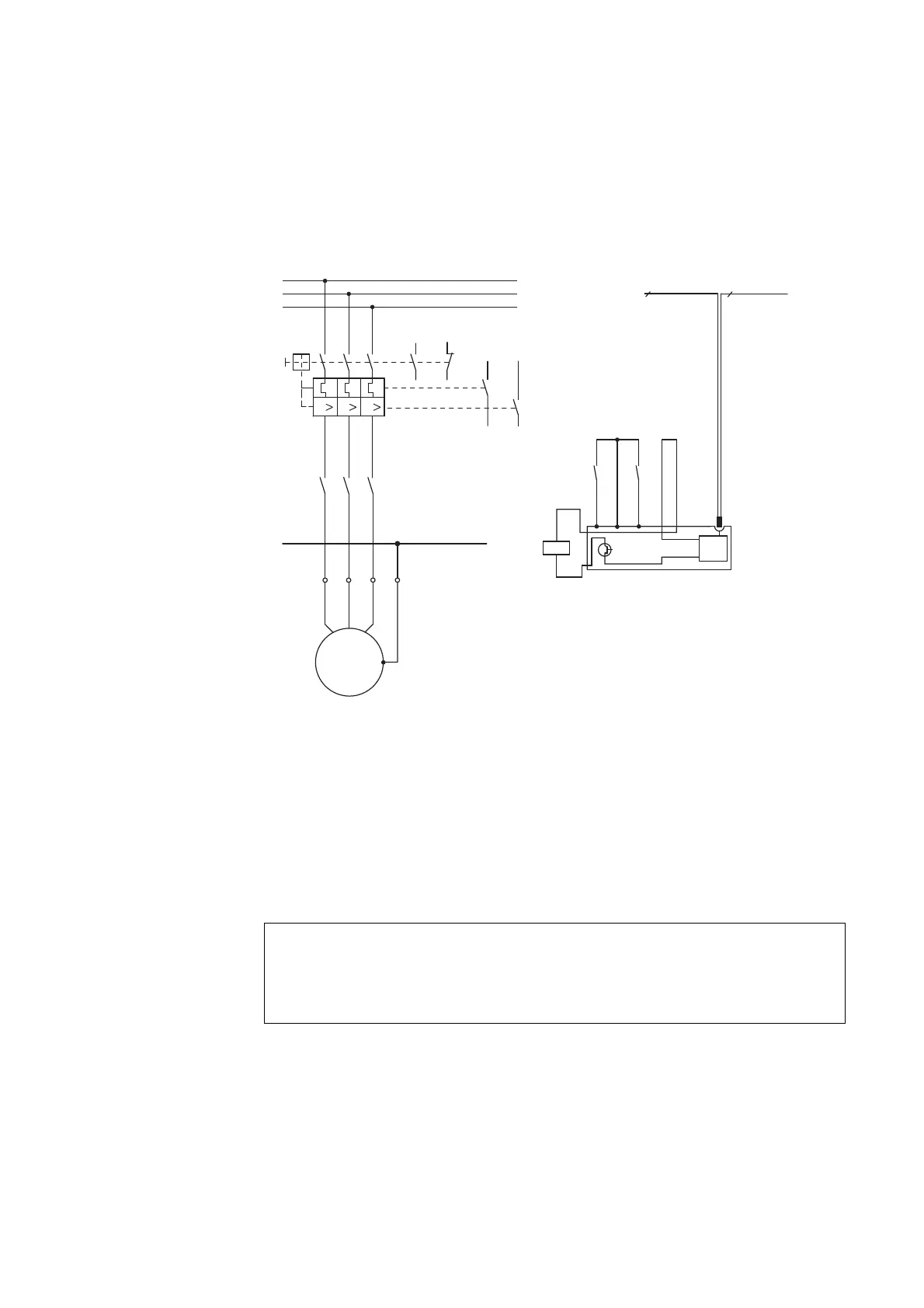
Figure 28: Circuit diagram of the direct starter
3.3.2 Reversing starter
The reversing starters are made up of a PKZM0 and two contactors DILM7 to
DILM32. One SmartWire-DT module each for DILM is mounted on both con-
tactors.
In addition to contactor control, two feedback signals can be sent to the
SmartWire-DT system on each SmartWire-DT module for DILM.
The "Enable" ⑧ auxiliary contact is factory fitted with a link, → Figure 30. For
the electrical interlocking of the two contactors this link is removed and the
auxiliary breaker (contacts 21-22) of the other contactor is linked in as a
potential-free contact.
→
Use of the 1-0-A switch for the electrical switching on or off of
the contactor is ensured only when the SmartWire-DT module
for DILM is supplied via the SmartWire-DT connecting cable.
8
SmartWire-DT
L1
L2
L3
-Q11
X1
531
531
642
WVU
642
PE
WVUPE
PE
M
-M1
3 ~
III
-Q1
1.211.13
1.22
1.14
4.43
4.13
4.44
4.14
-Q1 -Q1
4.43
4.44
1.13
1.14
-Q11
X1X0 X2 X3 X4
8
A1
A2
“+” “I >”
24 V
0 V
DC
ATTENTION
The SmartWire-DT modules for DILM drive the contactors so
that the terminals A1-A2 of the contactors need no further wir-
ing, with the exception of the DILM12-XEV link.

 Loading...


