2 I/O modules EU5E-SWD…
2.8 Digital module EU5E-SWD-4D4D
SmartWire-DT module IP20 01/20 MN05006001Z-EN www.eaton.com 33
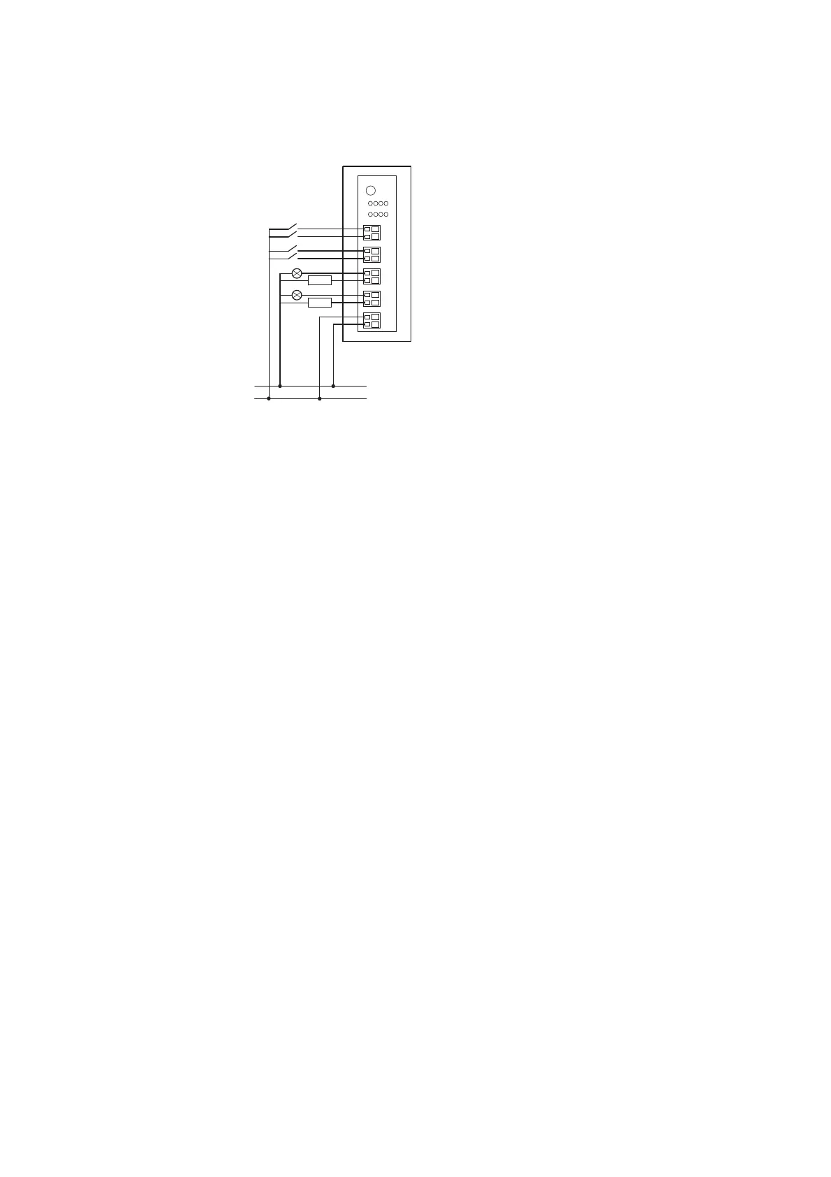
Figure 13: Connecting inputs/outputs and power supply
2.8.4 Installation
▶ Connect the sensors to the corresponding inputs I0 to I3.
▶ Connect the reference potential 0 V DC to connection 0V.
▶ Connect the actuators to the corresponding output Q0 to Q3.
▶ Connect the 24 V DC supply voltage for the outputs to the 24 V connec-
tion terminal
2.8.5 Parameterization
Depending on the coordinator being used, the module's parameters will
need to be configured in the programming system or in the SWD-Assist plan-
ning and commissioning program.
2.8.6 Fieldbus-specific characteristics
Fieldbus EtherCAT
Please note the general information for configuring parameters
→ Chapter 12 “Using SWD modules with the EtherCAT field bus”, page
247, particularly
→ Section , „Device options“, page 247..
2.8.7 Programming
The module has two input bytes and one output byte at its disposal.
0 V
24 V DC
24 V
0 V
1
2 30Q
1230I
Q1
Q0
Q3
Q2
I1
I0
I3
I2

 Loading...


