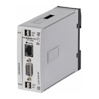
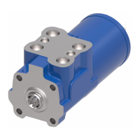
8 SL4-SWD and SL7-SWD base modules for signal towers
8.3 Engineering
SmartWire-DT module IP20 01/20 MN05006001Z-EN www.eaton.com 205
8.3 Engineering
Base modules SL4-SWD and SL7-SWD require two supply voltages.
The first one - the 15-V U
SWD
supply voltage for controlling the base modules
- is provided by the SWD line.
The second one - the 24-V supply voltage for the light/acoustic modules - can
be provided in one of two ways:
• The SWD line can carry the 24-V U
AUX
supply voltage.
To achieve this, either a 24 VDC supply voltage has to be fed into the
AUX terminals on the SmartWire-DT coordinator or an EU5C-SWD-PF1-1
or EU5C-SWD-PF1-2 power module has to be connected to the SWD line
upstream of the base module.
• An external 24 VDC power supply can be connected using the base mod-
ule's push-in terminals.
Jumpers are used in order to choose which of the supply voltages provided
will be supplied to the light/acoustic modules.
The signal and supply cables are connected to the SmartWire-DT ribbon
cable using a SmartWire-DT SWD4-8MF2 blade terminal.
The push-in terminals are designed to accommodate wires with a gauge of
AWG24 to AWG16 and wires with a cross-sectional area of 0.25 to 1.5 mm
2
.
The current requirement is:
• U
SWD
(15 V DC): 26 mA,
• U
AUX
(24 V DC) 254.
→
Please calculate your SmartWire-DT system's total power con-
sumption and, if necessary, add an additional EU5C-SWD-PF2-1
feeder module. For more information, please refer to the man-
ual "SmartWire-DT The system", MN05006002Z.
→
For data regarding the SmartWire-DT modules' current con-
sumption, please refer to the tables in the appendix on pages
253 and 254.

 Loading...


