1 EU5C-SWD-PF1-1, EU5C-SWD-PF2-1 power modules
1.3 EU5C-SWD-PF2-1
SmartWire-DT module IP20 01/20 MN05006001Z-EN www.eaton.com 19
1.3.2 Engineering
1.3.2.1 Area of application of the SmartWire-DT power module EU5C-SWD-PF2-1
• The supply for the modules installed in the SmartWire-DT network is no
longer sufficient (power consumption > 0.7 A).
• The supply for the contactors installed in the SmartWire-DT network is no
longer sufficient (power consumption of the contactors > 72 W / 3 A).
• A selective emergency shutdown of individual contactor groups or motor
starter groups is required (→ Chapter 3, „Switching on
DIL-SWD-32-001, DIL-SWD-32-002 contactors“, Page 65).
1.3.3 Installation
The SmartWire-DT power module EU5C-SWD-PF2 is envisaged for mounting
on a top-hat rail.
▶ Mount the module on the top hat rail.
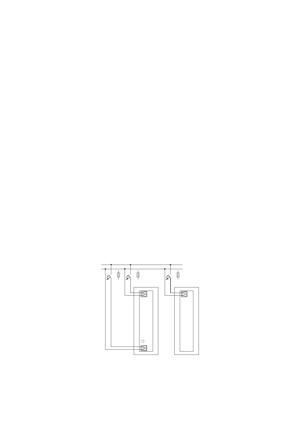
▶ Connect the 24 V DC voltage to the terminals POW on the front of the
module.
▶ If necessary, reconnect the 24 V DC voltage for the contactor coils to the
terminals
AUX.
▶ Connect the 8 pole SmartWire-DT cable to the SWD In socket. The con-
tinuation to the next SmartWire-DT module is from the SWD Out socket.
The connection terminals are suitable for cables AWG24 to AWG16 and flex-
ible conductors with a cross section of 0.5 to 1.5 mm
2
.
Figure 4: Terminal capacities
• flexible, cross-section 0.25 mm² to 1.5 mm², with the ferrule (minimum
length 8 mm)
→
With a SmartWire-DT power module a second incoming unit for
the contactor coil control voltage can be made at another posi-
tion in the SmartWire-DT network.
24V
0V
POW
AUX
24V
0V
AUX
24V
0V
24 V DC
0 V
F1 F2 F2

 Loading...


