8 SL4-SWD and SL7-SWD base modules for signal towers
8.4 Installation
SmartWire-DT module IP20 01/20 MN05006001Z-EN www.eaton.com 209
Follow the steps below to connect SmartWire-DT:
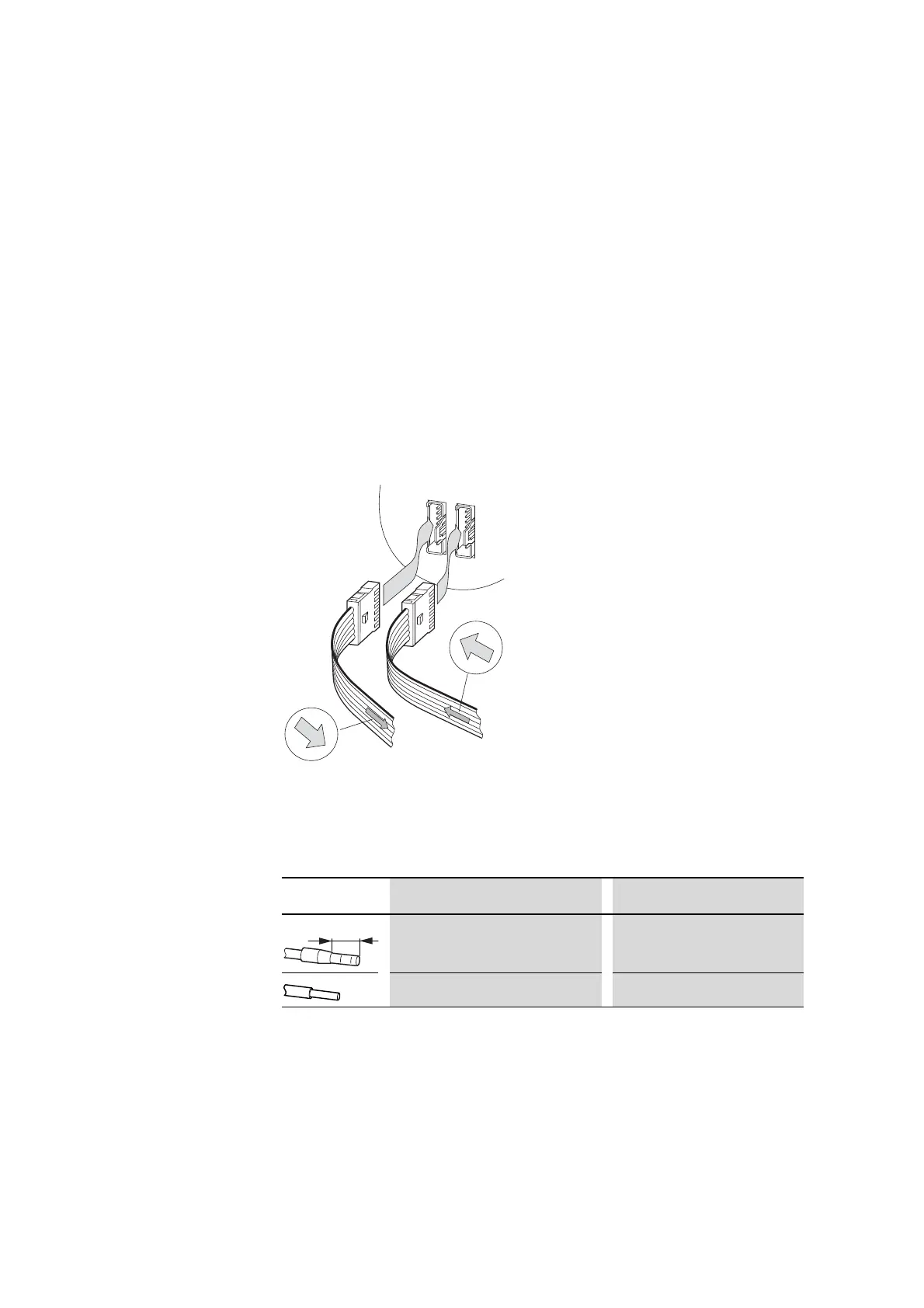
▶ Plug the blade terminal of the SWD ribbon cable coming from the Smart-
Wire-DT coordinator's direction into the base module's X1(IN) socket.
▶ Plug the blade terminal of the SWD ribbon cable going to the next mod-
ule into the base module's X2(OUT) socket.
▶ If there are no more SmartWire-DT modules after the base module, ter-
minate the SWD line with an SWD4-RC8-10 bus termination resistor.
To do this, crimp a blade terminal onto the ends of a ribbon cable. Place
the bus termination resistor on the blade terminal towards which the
black arrow on the ribbon cable is pointing. Plug the blade terminal away
from which the black arrow on the ribbon cable is pointing into the base
module's X2 socket. Make sure to connect the SWD ribbon cable cor-
rectly. For detailed information, refer to the "SmartWire-DT The system",
MN05006002Z manual.
Figure 75: Plugging in the coming and going SWD ribbon cables
8.4.4 Terminal capacities
Table 58: External auxiliary power, 24 V DC
SWD4-8SF2
SWD4-8SF2
SWD4-...LF-...
(OUT) X2
X1 (IN)
Figure Version Terminal capacity
Flexible with ferrule 0.25 - 1.5 mm² (Minimum length 8 mm)
solid 0.25 to 1.5 mm² (AWG 24 - 16)

 Loading...


