3 Switching on DIL-SWD-32-001, DIL-SWD-32-002 contactors
3.3 Engineering
SmartWire-DT module IP20 01/20 MN05006001Z-EN www.eaton.com 73
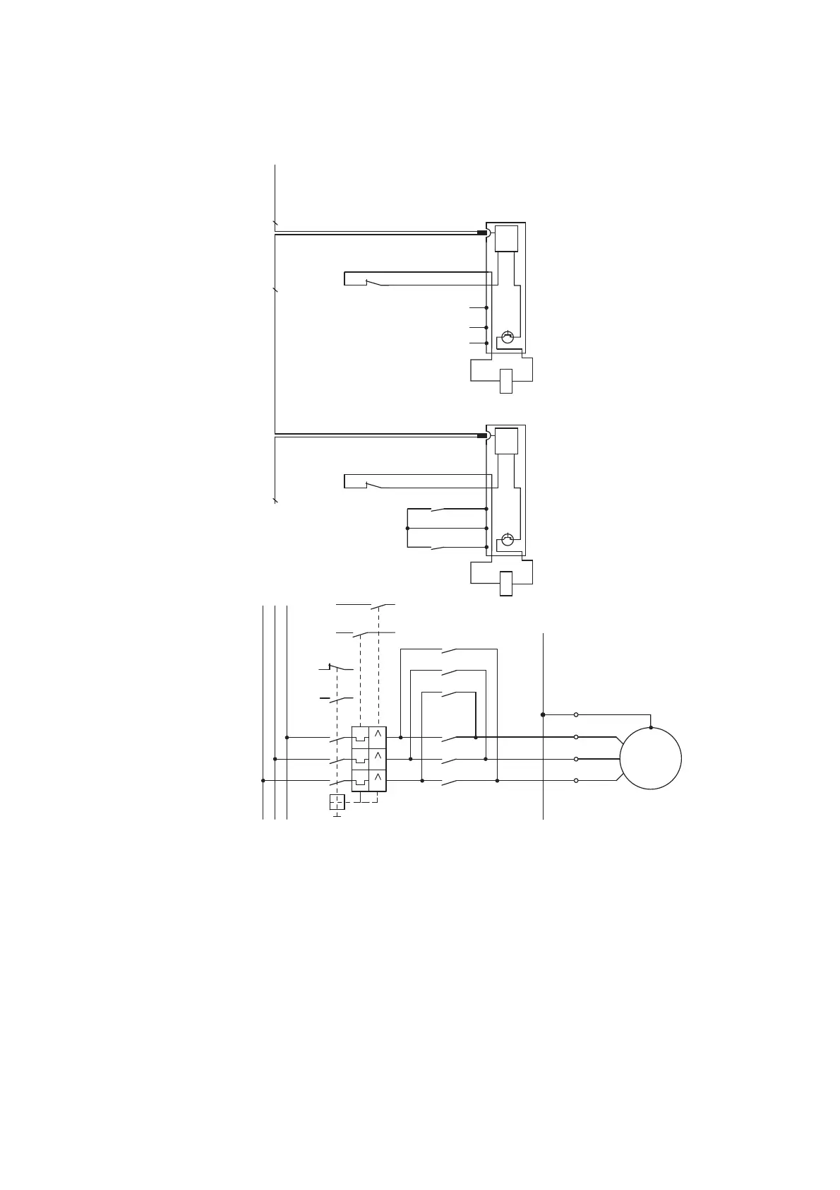
Figure 30: Circuit diagram of the reversing starter
3.3.3 Safety-related applications
For most applications, disconnection in the event of an emergency or the dis-
connection by the opening of the protective doors is also required in addition
to normal operational switching.
The SmartWire-DT system is not designed for the transfer of safety relevant
signals. Using the following configuration the system SmartWire-DT can
however be used for safety relevant switch-offs.
L1
L2
L3
-Q11
-Q12 -Q11
X1
5 3 1
5 3 1
6 4 2
W V U
6 4 2
-Q12
5 3 1
6 4 2
PE
W V U
PE
PE
M
-M1
3 ~
III
-Q1
1.21 1.13
1.22
21
22
1.14
4.43
4.13
4.44
4.14
-Q1 -Q1
4.43
4.44
1.13
1.14
-Q11
X1 X0 X2 X3 X4
8
21
22
8
SmartWire-DT
A1
A2
-Q12
X1 X0 X2 X3 X4
8
SmartWire-DTSmartWire-DT
A1
A2
“+” “I >”
24 V
0 V
DC
24 V
0 V
DC

 Loading...


