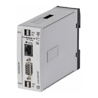
6 PKE-SWD-CP, Connection for circuit-breaker PKE
6.6 Exchange of modules
144 SmartWire-DT module IP20 01/20 MN05006001Z-EN www.eaton.com
6.6 Exchange of modules
After replacing the modules and turning on the voltage, you will have to
press the configuration button. When this is done, the new module will be
assigned an address.
6.7 Device status
The individual SmartWire-DT modules indicate their device status with the
aid of a diagnosis LED. The diagnostics LED can have the following states:
Table 24: Diagnostic messages of the SmartWire-DT status LED
6.8 Parameterization
Depending on the coordinator being used, the module's parameters will
need to be configured in the programming system or in the SWD-Assist plan-
ning and commissioning program.
6.9 Fieldbus-specific characteristics
Field bus Ethercat
Please note the general information for configuring parameters
→ Chapter 12 “Using SWD modules with the EtherCAT field bus”, page
247.
ATTENTION
The order of the SmartWire-DT units must not be altered.
DANGER
The SmartWire-DT module must not be swapped
unless the entire SmartWire-DT system has been switched off
first.
Designation Color State Message
Ready Green Continuous light Device is operating error-free.
Flashing (1 Hz) • Addressing process in progress
• After the coordinator is powered on
• after actuation of the configuration button on the coordinator
• Module not in current configuration
• invalid type
Flashing (3 Hz) • Communication to trip block PKE is interrupted
• The trip block is not of part no. PKE-XTU(W)ACP-…

 Loading...


