2 I/O modules EU5E-SWD…
2.9 Digital module EU5E-SWD-4D4D-R
36 SmartWire-DT module IP20 01/20 MN05006001Z-EN www.eaton.com
2.9 Digital module EU5E-SWD-4D4D-R
2.9.1 INTRODUCTION
The SmartWire-DT I/O module EU5E-SWD-4D4D-R provides four digital
inputs I0 to I3 and four digital outputs Q0 to Q3.
Diverse sensors can be integrated into the SmartWire-DT network via the
inputs.
The short-circuit proof outputs are used to drive actuators.
The module is retentive, i.e., the outputs' state will be maintained even in the
event of a loss of voltage or communications or if the controller is stopped.
The inputs'/outputs' status is indicated with the help of LEDs.
Finally, the SmartWire-DT diagnostic LED is used to signal the network's/
module's status.
2.9.2 Surface mounting
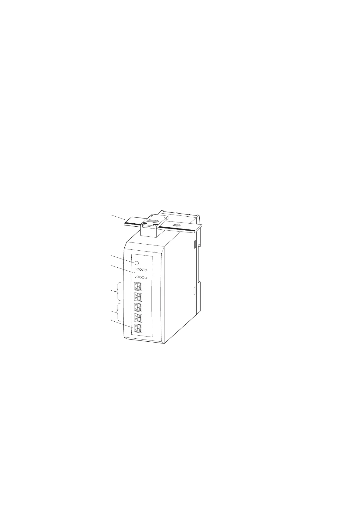
Figure 14: Connections of the modules EU5E-SWD-4D4D-R
2.9.3 Engineering
The maximum current draw for each output is 0.5 A. The outputs are short-
circuit proof. On short circuit the SmartWire-DT diagnostics LED flashes and
the diagnostic bit is set in the user program. When the short circuit is
removed, the outputs are ready for operation again.
By configuring the module appropriately, the outputs' behavior can be
changed in such a way that the output state will not be reset automatically in
certain cases, such as a communication error on the field bus or the PLC
stopping.
a SmartWire-DT cable with external device plug
b SmartWire-DT diagnostics LED
c Status LEDs of the inputs and outputs
d I0 – I3 (inputs)
e Q0 – Q3 (outputs)
f 0-V-24-V connection

 Loading...


