2 I/O modules EU5E-SWD…
2.11 Digital module EU5E-SWD-X8D
46 SmartWire-DT module IP20 01/20 MN05006001Z-EN www.eaton.com
2.11 Digital module EU5E-SWD-X8D
2.11.1 INTRODUCTION
SmartWire-DT I/O module EU5E-SWD-X8D provides eight digital outputs Q0
to Q7.
The outputs are used to operate actuators.
The outputs' status is indicated with the help of LEDs.
The SmartWire-DT diagnostic LED is used to signal the network's/module's
status.
2.11.2 Surface mounting
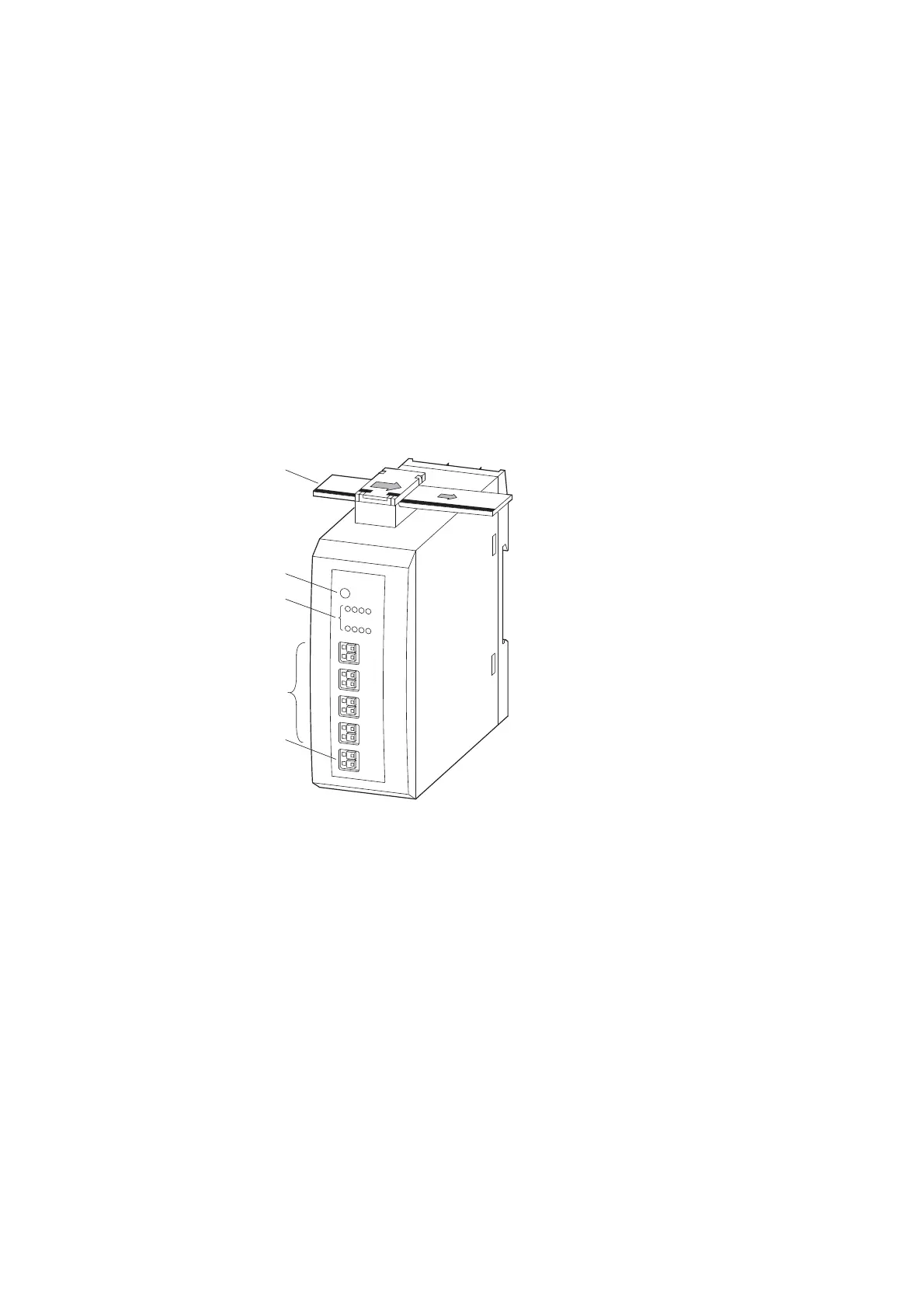
Figure 18: Layout of module EU5E-SWD-X8D
2.11.3 Engineering
The maximum current draw for each output is 0.5 A. The outputs are short-
circuit proof. On short circuit the SmartWire-DT diagnostics LED flashes and
the diagnostic bit is set in the user program. When the short circuit is
removed, the supply voltage is automatically applied again.
a
b
c
d
e
a SmartWire-DT cable with external device plug
b SmartWire-DT diagnostics LED
c Status LEDs of the outputs
d Q0 – Q7 (outputs)
e 0-V-24-V connection

 Loading...


