Menu 4
Parameter
structure
Keypad and
display
Parameter
x.00
Parameter
description format
Advanced parameter
descriptions
Macros
Serial comms
protocol
Electronic
nameplate
Performance RFC mode
100 Unidrive SP Advanced User Guide
www.controltechniques.com Issue Number: 10
In regen mode it is possible to produce some current in the x axis of the reference frame so that the regen unit can be made to produce or consume
reactive power. This parameter defines the level of reactive current as a percentage of the regen mode rated current (Pr 5.07). Positive reactive
current produces a component of current flowing from the supply to the drive at the regen unit terminals that lags the respective phase voltage, and
negative reactive current produces a component of current that leads the respective voltage. It should be noted that the maximum current in regen
mode is limited to DRIVE_CURRENT_MAX, and so the drive applies a limit to this parameter (REGEN_REACTIVE_MAX) to limit the current
magnitude. Therefore the symmetrical current limit (Pr 4.07) must be reduced below its maximum value before this parameter can be increased from
zero.
The torque offset is added to the torque reference when Pr 4.10 is one. The torque offset is updated every 4ms when connected to an analog input,
and so Pr 4.08 should be used for fast updating if required.
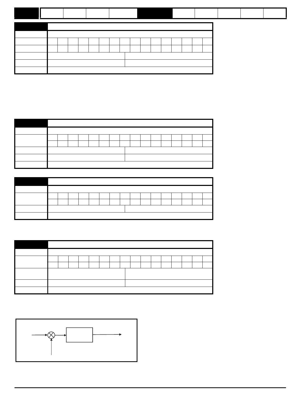
Open loop
If this parameter is 0 normal frequency control is used. If this parameter is set to 1 the current demand is connected to the current PI controller giving
closed loop torque/current demand as shown below. The current error is passed through proportional and integral terms to give a frequency reference
which is limited to the range ±SPEED_FREQ_MAX .
4.08 Reactive current reference
Drive modes Regen
Coding Bit SP FI DE Txt VM DP ND RA NC NV PT US RW BU PS
11 11
Range Regen ±REGEN_REACTIVE_MAX %
Default Regen 0.0
Update rate 4ms read
4.09 Torque offset
Drive modes Open-loop, Closed-loop vector, Servo
Coding
Bit SP FI DE Txt VM DP ND RA NC NV PT US RW BU PS
11 11
Range Open-loop, Closed-loop vector, Servo ±USER_CURRENT_MAX %
Default Open-loop, Closed-loop vector, Servo 0.0
Update rate 4ms read
4.10 Torque offset select
Drive modes Open-loop, Closed-loop vector, Servo
Coding
Bit SP FI DE Txt VM DP ND RA NC NV PT US RW BU PS
111
Default Open-loop, Closed-loop vector, Servo 0
Update rate 4ms read
4.11 Torque mode selector
Drive modes Open-loop, Closed-loop vector, Servo
Coding
Bit SP FI DE Txt VM DP ND RA NC NV PT US RW BU PS
111
Range
Open-loop
Closed-loop vector and Servo
0 to 1
0 to 4
Default Open-loop, Closed-loop vector, Servo 0
Update rate 4ms read
P Pr
4.13
I Pr
4.14
Current
demand
Active
current
Frequency
reference
+
-

 Loading...


