Parameter
structure
Keypad and
display
Parameter
x.00
Parameter
description format
Advanced parameter
descriptions
Macros
Serial comms
protocol
Electronic
nameplate
Performance RFC mode
Menu 3
All modes
Unidrive SP Advanced User Guide 67
Issue Number: 10 www.controltechniques.com
Parameters common to open-loop and closed-loop modes
Provided the set-up parameters for the drive encoder are correct this parameter shows the encoder speed in rpm.
It should be noted that the value shown by this parameter is measured over a 16ms sliding window period (in the same way as Pr 3.02), and so the
ripple in this parameter accessible via comms or by a Solutions Module is as defined for Pr 3.02. The FI attribute for this parameter is set, and so
further filtering is applied when this parameter is viewed with one of the drive keypads.
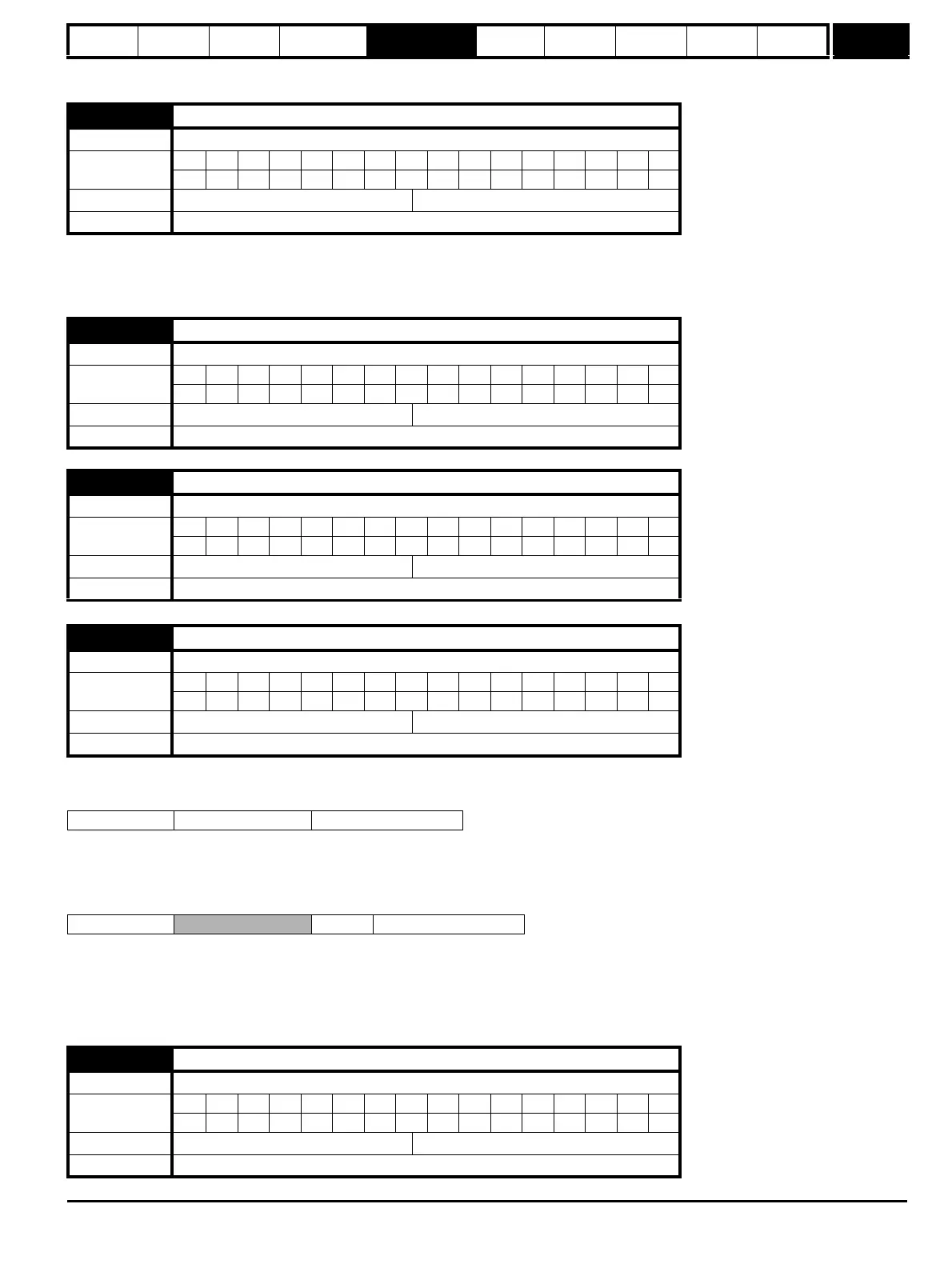
These parameters effectively give the encoder position with a resolution of 1/2
32
ths of a revolution as a 48 bit number as shown below.
Provided the encoder set-up parameters are correct, the position is always converted to units of 1/2
32
ths of a revolution, but some parts of the value
may not be relevant depending on the resolution of the feedback device. For example a 1024 line digital encoder produces 4096 counts per
revolution, and so the position is represented by the bits in the shaded area only.
When the encoder rotates by more than one revolution, the revolutions in Pr 3.28 increment or decrement in the form of a sixteen bit roll-over counter.
If an absolute position feedback device (except an encoder with commutation signals) is used the position is initialized at power-up with the absolute
position. If a multi-turn absolute encoder is used the revolution counter is also initialized with the absolute revolutions at power-up.
If a linear encoder is used the turns information is used to represent movement by the number of poles defined by Pr 5.11 (or 21.11 for motor map 2).
Therefore if the number of poles is set to two, one revolution is the movement by one pole pitch.
3.27
Drive encoder speed feedback
Drive modes Open-loop, Closed-loop vector, Servo
Coding
Bit SP FI DE Txt VM DP ND RA NC NV PT US RW BU PS
11111
Range Open-loop, Closed-loop vector, Servo ±40,000.0 rpm
Update rate 4ms write
3.28
Drive encoder revolution counter
Drive modes Open-loop, Closed-loop vector, Servo
Coding
Bit SP FI DE Txt VM DP ND RA NC NV PT US RW BU PS
11111
Range Open-loop, Closed-loop vector, Servo 0 to 65,535 revolutions
Update rate 4ms write
3.29
Drive encoder position
Drive modes Open-loop, Closed-loop vector, Servo
Coding
Bit SP FI DE Txt VM DP ND RA NC NV PT US RW BU PS
11111
Range Open-loop, Closed-loop vector, Servo
0 to 65,535 (1/2
16
ths of a revolution)
Update rate 4ms write
3.30
Drive encoder fine position
Drive modes Open-loop, Closed-loop vector, Servo
Coding
Bit SP FI DE Txt VM DP ND RA NC NV PT US RW BU PS
11111
Range Open-loop, Closed-loop vector, Servo
0 to 65,535 (1/2
32
ths of a revolution)
Update rate 4ms write
47 32 31 16 15 0
Revolutions Position Fine position
47 32 31 20 19 16 15 0
Revolutions
Position Fine position
3.31
Drive encoder marker position reset disable
Drive modes Open-loop, Closed-loop vector, Servo
Coding
Bit SP FI DE Txt VM DP ND RA NC NV PT US RW BU PS
111
Default Open-loop, Closed-loop vector, Servo 0
Update rate Background read

 Loading...


