Parameter
structure
Keypad and
display
Parameter
x.00
Parameter
description format
Advanced parameter
descriptions
Macros
Serial comms
protocol
Electronic
nameplate
Performance RFC mode
Menu 3
Regen
Unidrive SP Advanced User Guide 87
Issue Number: 10 www.controltechniques.com
When regen mode is selected Pr 3.08 is the destination from digital I/O2 (T25) with the I/O set up as an input as default. This input, or an alternative
input, should be connected to an auxiliary contact on the contactor so that it follows the state of the contactor..
When the unit has been enabled and successfully synchronized this bit will become active. If the regen unit attempts to re-synchronize or trips, this bit
becomes inactive. When regen mode is selected this bit is routed to a digital I/O1 (T24) with the I/O set up as an output as default. The output, or an
alternative output, should be used to enable the motor drive(s) connected to the DC Bus link of the regen unit.
Power feed-forward compensation can be used to reduce the transient DC Bus link voltage produced when a fast load transient occurs on drives
connected to the Regen unit. 100.0% power feed-forward is equivalent to an active current of Kc / 0.45 (i.e. over current trip level) and an AC terminal
peak phase voltage equal to DC_VOLTAGE_MAX / 2. This scaling is the same as the power output from Pr 5.03 when high speed output mode is
used (see Menu 7). Therefore an analog output of the drive supply the load and analog input 2 or 3 of the drive acting as the supply Regen unit can
be connected together to give power feed-forward compensation without further scaling if the two drives are of equal rating. If the ratings are different
the analog input scaling must be used to give the correct power feed-forwards, where the scaling is given by Load drive Kc / Regen unit Kc.
This parameter defines the strategy used for current trimming in regen mode. If Pr 3.11 = 0 then current trimming is only carried out once after power-
up. If Pr 3.11 = 1 current trimming is carried out after power-up and then before the drive runs each time it is enabled.
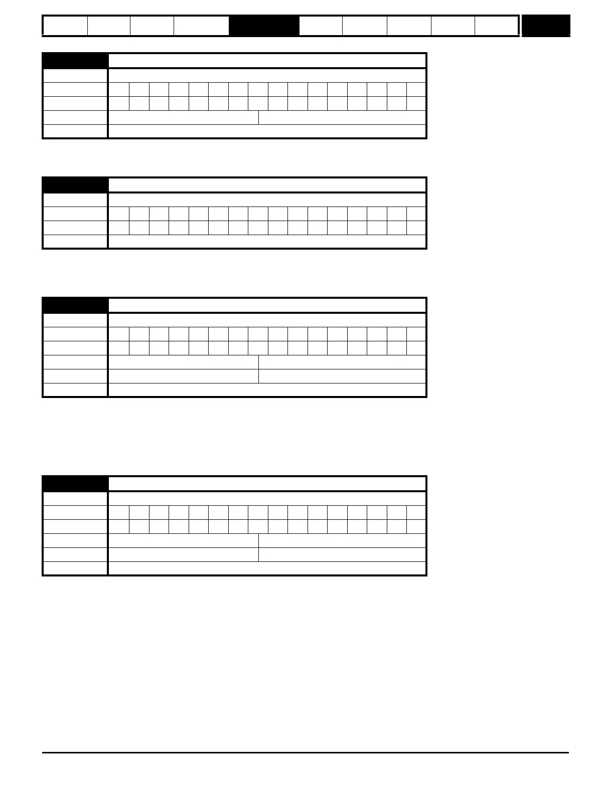
3.08
Contactor closed
Drive modes Regen
Coding Bit SP FI DE Txt VM DP ND RA NC NV PT US RW BU PS
111
Default Regen 0
Update rate 4ms read
3.09
Enable motor drive
Drive modes Regen
Coding Bit SP FI DE Txt VM DP ND RA NC NV PT US RW BU PS
111
Update rate 4ms write
3.10
Power feed-forward compensation
Drive modes Regen
Coding Bit SP FI DE Txt VM DP ND RA NC NV PT US RW BU PS
11 1
Range Regen ±100.0%
Default Regen 0.0
Update rate 4ms read
3.11
Current trimming mode
Drive modes Regen
Coding Bit SP FI DE Txt VM DP ND RA NC NV PT US RW BU PS
111
Range Regen 0 to 1
Default Regen 0
Update rate 4ms read

 Loading...


