Parameter
structure
Keypad and
display
Parameter
x.00
Parameter
description format
Advanced parameter
descriptions
Macros
Serial comms
protocol
Electronic
nameplate
Performance RFC mode
Menu 3
All modes
Unidrive SP Advanced User Guide 79
Issue Number: 10 www.controltechniques.com
The actual encoder comms buffer is 16 bytes long and any messages that exceed this length (including the checksum added for Hiperface) will cause
an error. The status flags are defined as follows:
SC.Hiper type encoders
The Stegmann Hiperface comms protocol is an asynchronous byte based system. Up to 15 bytes of data can be written to the buffer. The first byte
should be the encoder address. The checksum will be calculated by the drive and added to the end of the message before the message is transmitted
to the encoder. The drive checks the checksum of the received message. If successfully received, the receive message can be read via the receive
register (Pr 90.23) including the address and the checksum received from the encoder. It should be noted that the encoder must be set up for 9600
baud, 1 start bit, 1 stop bit and even parity (default set-up) for the encoder comms to operate with the drive. Also the data block security should not be
enabled in the encoder if the drive encoder nameplate system is to operate correctly.
The following commands are supported:
Example of a Hiperface transfer: read position
Disable drive encoder position check by setting Pr 90.21 to one. This should be set back to zero at the end of the transfer if encoder position checking
is required.
Transfer the "read position" message to the encoder comms buffer by writing the sequence of words shown in the table below to Pr 90.22. A check
should be carried out before each word is written to ensure that the parameter is zero (i.e. the drive has taken any previous data).
As bit 14 of the second word is set to one the drive will add the checksum and transfer this message to the encoder. When the encoder response has
been received by the drive the first byte of the message will be placed in the least significant byte of Pr 90.23 and bit 15 will be set to one. This data
should be read and the parameter cleared so that the drive will put the next byte into this parameter. The sequence of data that should appear in
Pr 90.23 for an encoder with an address of 0x40 and a position of 0x03, 0x59, 0x63, 0x97 is shown in the table below.
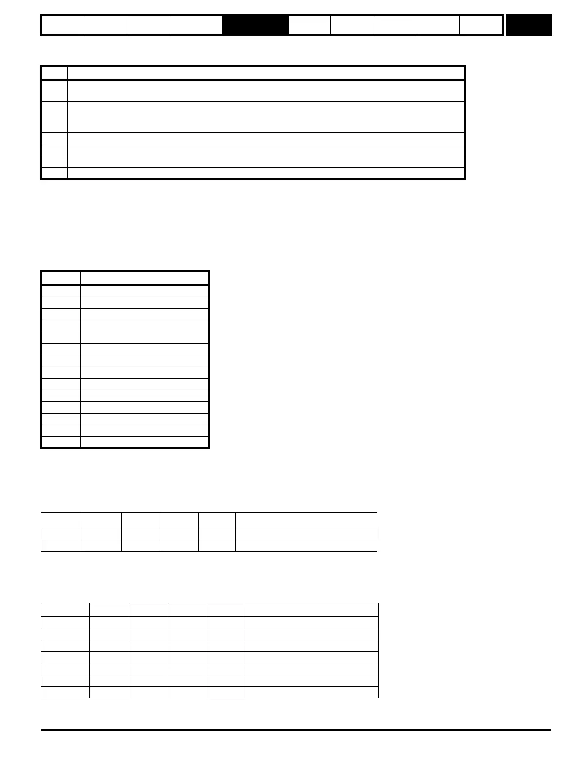
Bit Meaning
0
The number of bytes put into the transmit buffer is not consistent with the expected message length.
(Hiperface only)
1
The number of bytes written to the transmit buffer, or the expected length of the store data transmit message, or the
expected length of a read data message have exceed the length of the buffer.
(Hiperface only)
2 The command code is not supported.
3 The encoder has signalled an error.
4 There was an error in the checksum/CRC of the received message.
5 A timeout occurred.
Code Command
0x42 Read position
0x43 Set position
0x44 Read analog value
0x46 Read counter
0x47 Increment counter
0x49 Clear counter
0x4a Read data (maximum of 10 bytes)
0x4b Store data (maximum of 9 bytes)
0x4c Data field status
0x4d Create a data field
0x4e Available memory
0x50 Read encoder status
0x52 Read type
0x53 Reset encoder
Bit 15 Bit 14 Bit 13 Data
0xa0ff 1 0 1 0xff Broadcast message so address = 0xff
0xc042 1 1 0 0x42 Read position command
Bit 15 Bit 14 Bit 13 Data
0x8040 1 0 0 0x40 Encoder address
0x8042 1 0 0 0x42 Read position command
0x8003 1 0 0 0x03 Position byte 0 (MS byte)
0x8059 1 0 0 0x59 Position byte 1
0x8063 1 0 0 0x63 Position byte 2
0x8097 1 0 0 0x97 Position byte 3 (LS byte)
0xc0ac 1 1 0 0xac Checksum