Menu 6
Parameter
structure
Keypad and
display
Parameter
x.00
Parameter
description format
Advanced parameter
descriptions
Macros
Serial comms
protocol
Electronic
nameplate
Performance RFC mode
142 Unidrive SP Advanced User Guide
www.controltechniques.com Issue Number: 10
The trip log includes time stamping for individual trips provided Pr 6.49 is set to one. If Pr 6.28 is zero, the powered-up clock is used for time
stamping. If Pr 6.28 is one, the run time clock is used for time stamping. It should be noted that changing this parameter clears the trip and trip time
logs.
This bit shows whether the drive is in the enable state or not.
Generally this will reflect the state of the enable input and shows the same value as Pr 8.09. However the disabled state can be forced by other
functions within the drive. Pr 8.09 will always follow the enable input state but the Pr 6.29 will be held at zero, indicating that the drive is forced into the
disable state by the following:
1. A digital input is routed to this parameter as described below to provide a fast disable and the input forces this parameter to zero.
2. Any of the following trips are active: OI.AC, PS.10V, PS.24V, OI.Br, OV.
Software V01.10.00 onwards
If the destination of one of the drive digital I/O (Pr 8.21 to Pr 8.26) is set to Pr 6.29 and the I/O is set as an input the state of the input does not affect
the value of this parameter as it is protected, however, it does provide a fast disable function. The secure disable input to the drive (T31) disables the
drive in hardware by removing the gate drive signals from the inverter IGBT's and also disables the drive via the software system. When the drive is
disabled by de-activating the secure disable input there can be a delay of up to 20ms. However, if a digital I/O is set up to provide the fast disable
function it is possible to disable the drive within 600us of de-activating the input. To do this the enable signal should be connected to both the secure
disable (T31) and to the digital I/O selected for the fast disable function. The state of the digital I/O including the effect of its associated invert
parameter is ANDed with the secure disable to enable the drive.
If the safety function of the Secure Disable input is required then there must not be a direct connection between the Secure Disable input (T31) and
any other digital I/O on the drive. If the safety function of the Secure Disable input and the fast disable function is required then the drive should be
given two separate independent enable signals. A safety related enable from a safe source connected to the Secure Disable input on the drive. A
second enable connected to the digital I/O on the drive selected for the fast disable function. The circuit must be arranged so that a fault which causes
the fast input to be forced high cannot cause the Secure Disable input to be forced high, including the case where a component such as a blocking
diode has failed.
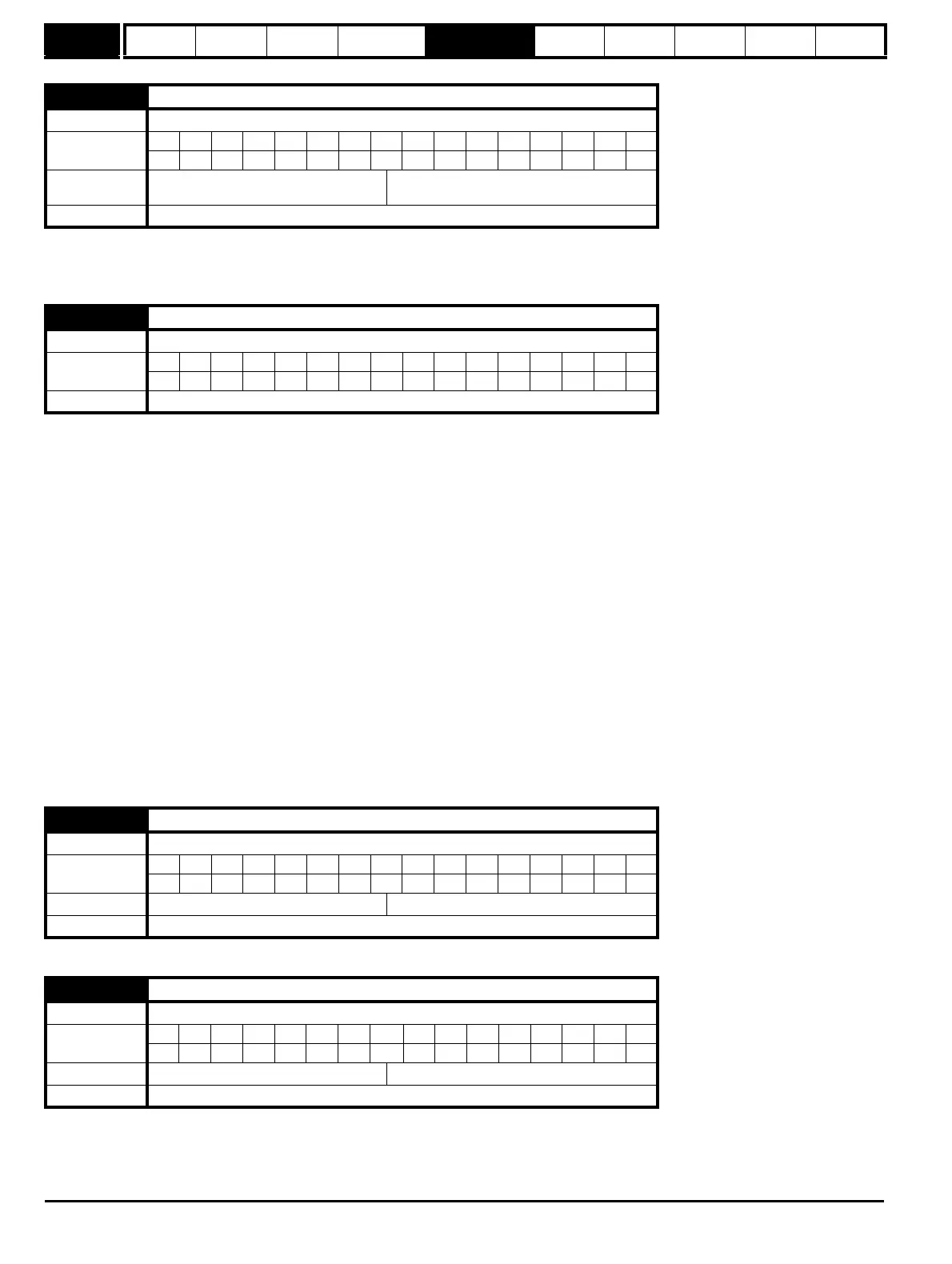
6.28 Select clock for trip log time stamping
Drive modes Open-loop, Closed-loop vector, Servo, Regen
Coding
BitSP FI DETEVMDPNDRANCNVPTUSRWBUPS
111
Default
Open-loop, Closed-loop vector, Servo,
Regen
0
Update rate Background read
6.29 Hardware enable
Drive modes Open-loop, Closed-loop vector, Servo, Regen
Coding
Bit SP FI DE TE VM DP ND RA NC NV PT US RW BU PS
111
Update rate 4ms write
6.30 Sequencing bit: Run forward
Drive modes Open-loop, Closed-loop vector, Servo
Coding
BitSP FI DETEVMDPNDRANCNVPTUSRWBUPS
111
Default Open-loop, Closed-loop vector, Servo 0
Update rate 4ms read
6.31 Sequencing bit: Jog
Drive modes Open-loop, Closed-loop vector, Servo
Coding
BitSP FI DETEVMDPNDRANCNVPTUSRWBUPS
111
Default Open-loop, Closed-loop vector, Servo 0
Update rate 4ms read

 Loading...


