Parameter
structure
Keypad and
display
Parameter
x.00
Parameter
description format
Advanced parameter
descriptions
Macros
Serial comms
protocol
Electronic
nameplate
Performance RFC mode
Menu 12
Unidrive SP Advanced User Guide 219
Issue Number: 10 www.controltechniques.com
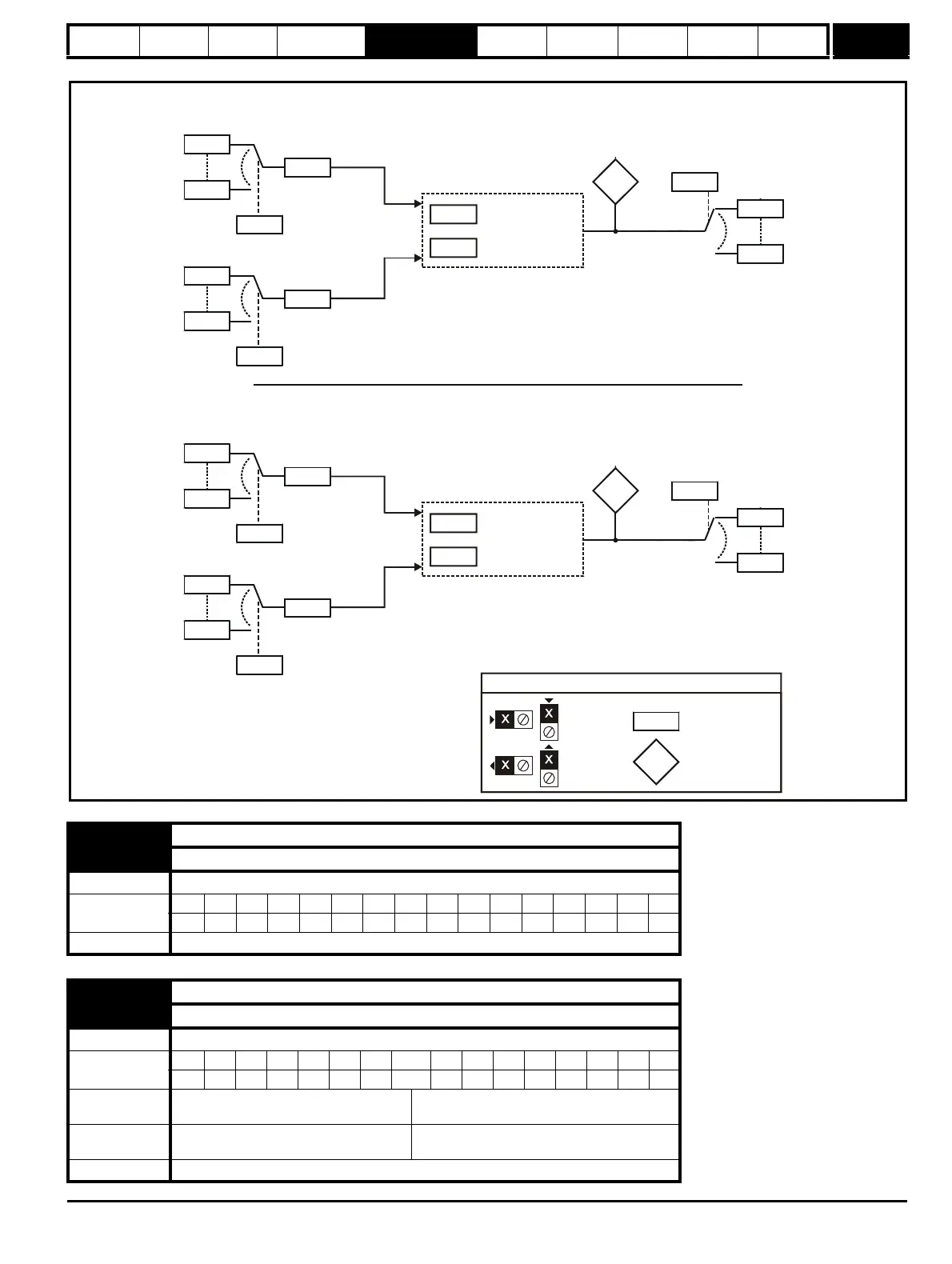
Figure 5-19 Menu 12 Logic diagram (continued)
12.01 Threshold detector 1 output
12.02 Threshold detector 2 output
Drive modes Open-loop, Closed-loop vector, Servo, Regen
Coding
Bit SP FI DE Txt VM DP ND RA NC NV PT US RW BU PS
1111
Update rate 4ms x number of menu 9 or 12 functions active write
12.03 Threshold detector 1 source
12.23 Threshold detector 2 source
Drive modes Open-loop, Closed-loop vector, Servo, Regen
Coding
Bit SP FI DE Txt VM DP ND RA NC NV PT US RW BU PS
2 1111
Range
Open-loop, Closed-loop vector, Servo,
Regen
Pr 0.00 to Pr 21.51
Default
Open-loop, Closed-loop vector, Servo,
Regen
Pr 0.00
Update rate Read on reset
Variable Selector 2
Variable selector 2
mode
Variable selector 2
control
12.30
12.35
??.??
??.??
12.28
12.33
Variable selector 2
input 1 source
Variable selector 2
input 1 scaling
??.??
??.??
12.29
12.34
Variable selector 2
input 2 source
Variable selector 2
input 2 scaling
Variable
Variable Selector 1
Variable selector 1
mode
Variable selector 1
control
12.10
12.15
??.??
Any variable
parameter
??.??
12.08
12.13
Variable selector 1
input 1 source
Variable selector 1
input 1 scaling
??.??
??.??
12.09
12.14
Variable selector 1
input 2 source
Variable selector 1
input 2 scaling
Variable
selector 1
output
indicator
Variable
selector 1
output
destination
Any variable
parameter
Any variable
parameter
Any variable
parameter
Any
unprotected
variable
parameter
Any
unprotected
variable
parameter
(RW)
parameter
Read-only (RO)
parameter
Input
terminals
Output
terminals

 Loading...


