Parameter
structure
Keypad and
display
Parameter
x.00
Parameter
description format
Advanced parameter
descriptions
Macros
Serial comms
protocol
Electronic
nameplate
Performance RFC mode
Menu 2
Unidrive SP Advanced User Guide 47
Issue Number: 10 www.controltechniques.com
Deceleration failure detection is provided to force the drive to change from the decelerating state to the appropriate stop state if the motor frequency
or speed is held at a constant level for 10s or more when the standard ramp voltage controller is active. When the drive is connected to a highly
inductive supply it is possible for the d.c. link voltage to rise as the motor frequency/speed falls. This rise in d.c. link voltage causes the standard ramp
d.c. link voltage controller to prevent any further deceleration.
In some applications with very high inertia, the motor frequency/speed must fall very slowly or else the power fed into the d.c. link will cause an over-
voltage trip. In these applications it may be necessary to disable the deceleration failure detection system by setting this parameter to 1.
The acceleration rate is selected as follows.
0 Ramp rate selection by terminal input
1 - 8 Ramp rate defined by parameter number, i.e. 1 = Pr 2.11, 2 = Pr 2.12, etc.
9 Ramp rate selection by Pr 1.50
When Pr 2.10 is set to 0 the acceleration ramp rate selected depends on the state of bit Pr 2.32 to Pr 2.34. These bits are for control by digital inputs
such that ramp rates can be selected by external control. The ramp rate selected depends on the binary code generated by these bits as follows:
When Pr 2.10 is set to 9 the appropriate acceleration rate is automatically selected depending on the value of Pr 1.50, and so an acceleration rate can
be programmed to operate with each reference. Since the new ramp rate is selected with the new reference, the acceleration applies towards the
selected preset if the motor needs to accelerate to reach the preset.
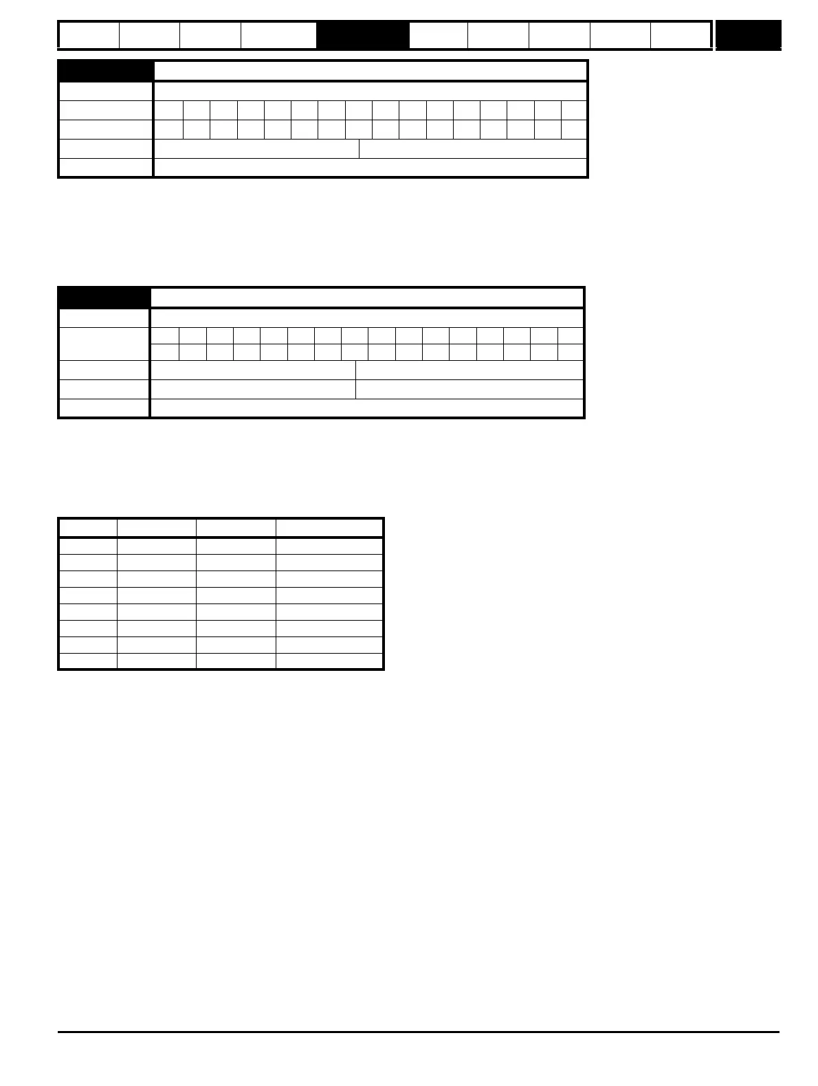
02.09 Deceleration failure detection
Drive modes Open-loop, Closed-loop vector, Servo
Coding Bit SP FI DETEVMDPNDRANCNVPTUSRWBUPS
111
Default Open-loop, Closed-loop vector, Servo 0
Update rate Background read
2.10 Acceleration rate selector
Drive modes Open-loop, Closed-loop vector, Servo
Coding
Bit SP FI DE Txt VM DP ND RA NC NV PT US RW BU PS
111
Range Open-loop, Closed-loop vector, Servo 0 to 9
Default Open-loop, Closed-loop vector, Servo 0
Update rate 4ms read
Pr 2.34 Pr 2.33 Pr 2.32 Ramp defined by
00 0 Pr 2.11
00 1 Pr 2.12
01 0 Pr 2.13
01 1 Pr 2.14
10 0 Pr 2.15
10 1 Pr 2.16
11 0 Pr 2.17
11 1 Pr 2.18

 Loading...


