Menu 5
Parameter
structure
Keypad and
display
Parameter
x.00
Parameter
description format
Advanced parameter
descriptions
Macros
Serial comms
protocol
Electronic
nameplate
Performance RFC mode
130 Unidrive SP Advanced User Guide
www.controltechniques.com Issue Number: 10
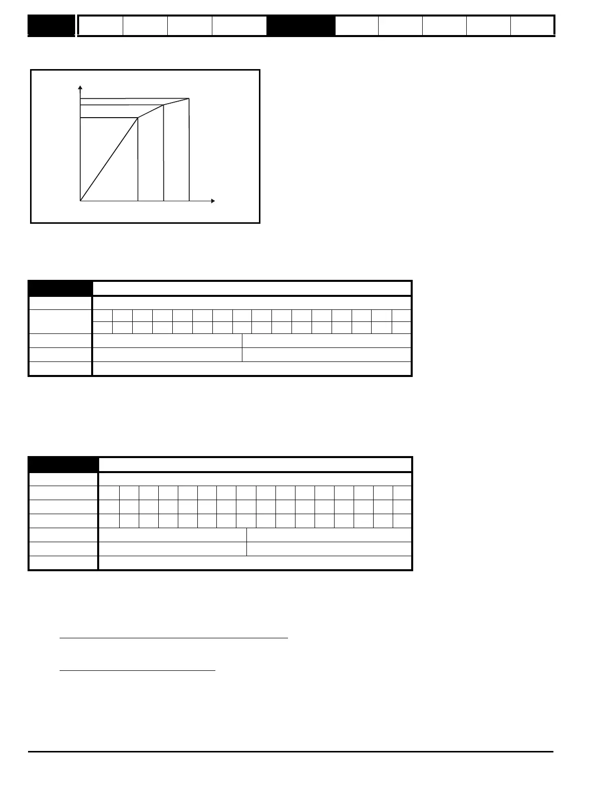
The drive can include the effects of saturation by representing the flux producing current to flux characteristic as a series of three lines as shown
below:
If Pr 5.29 and Pr 5.30 have their default values of 50 and 75, the characteristic becomes one line and there will be a linear relationship between the
drive estimate of flux and the flux producing current. If Pr 5.29 and Pr 5.30 are increased above 50 and 75 the drive estimate of flux can include the
effect of saturation. It is unlikely that information will be available to set up these parameters, and so the values are determined during the rotating
auto-tune test.
This parameter controls the gain of the voltage controller used for mains loss and standard ramp control. If the parameter is set to 1 the gain used is
suitable for applications where the drive is used alone. Higher values are intended for applications where the DC bus of each drive is connected in
parallel and the drive is used as a master for mains loss control. This is intended for use in applications where each drive is locked together using
open-loop frequency slaving. (If motors are locked together using digital-locking, using a master for mains loss control, it is unlikely that the system
will be stable during mains loss unless the power rating of the master is much higher than the combined rating of the slaves. This is due to the lag
created by the master motor inertia).
This parameter shows the motor torque per amp of active (torque producing) current used to calculate the speed controller gains when the automatic
set-up methods are active (i.e. Pr 3.17 = 1 or 2).
Closed-loop vector
The drive calculates the motor torque per amp of active current using the motor parameters as shown below assuming a motor efficiency of 90%.
Rated active current is the active current when the motor current is equal to the rated motor current and is defined at the start of the description of
menu 4.
Servo
The motor torque per amp (Kt) must be entered in this parameter by the user for the automatic gain calculation system to operate correctly, and to
allow the drive to calculate the correct inertia during an inertia auto-tune.
5.31 Voltage controller gain
Drive modes Open-loop, Closed-loop vector, Servo
Coding
Bit SP FI DE Txt VM DP ND RA NC NV PT US RW BU PS
111
Range Open-loop, Closed-loop vector, Servo 0 to 30
Default Open-loop, Closed-loop vector, Servo 1
Update rate Background read
5.32 Motor torque per amp (Kt)
Drive modes Closed-loop vector, Servo
Coding Bit SP FI DE TE VM DP ND RA NC NV PT US RW BU PS
CLV 21 1
SV 2 111
Range Closed-loop vector, Servo
0.00 to 500.00 NmA
-1
Default Servo 1.60
Update rate Background (1s) read
Kt =
√3 x Vrated x Irated x Rated power factor x Efficiency
Rated speed (rad s
-1
) x Rated active current
Kt =
√3 x Pr 5.09 x Pr 5.07 x Pr 5.10 x 0.9
(2π x Pr 5.08 / 60) x Rated active current
i_mag (%)
flux (%)
50 75 100
100%
Pr
5.30
Pr
5.29

 Loading...


