Parameter
structure
Keypad and
display
Parameter
x.00
Parameter
description format
Advanced parameter
descriptions
Macros
Serial comms
protocol
Electronic
nameplate
Performance RFC mode
Menus 15 to 17
SM-I/O 120V
Unidrive SP Advanced User Guide 313
Issue Number: 10 www.controltechniques.com
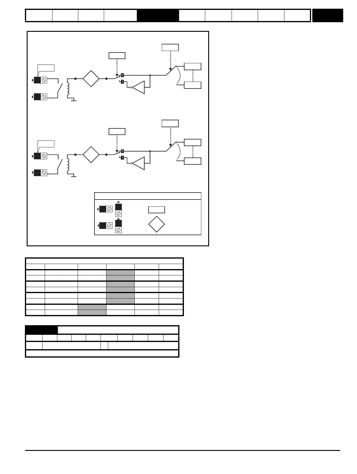
Figure 5-27 Relay logic diagram
The menu for the relevant slot appears for the new Solutions Module category with the default parameter values for the new category. When no
Solutions Module is installed in the relevant slot this parameter is zero. When a Solutions Module is installed this parameter displays the identification
code.
206: SM-I/O 120V
The new parameters values are not stored in EEPROM until the user performs a parameter save. When parameters are saved by the user in the drive
EEPROM the option code of the currently installed Solutions Module is saved in EEPROM. If the drive is subsequently powered-up with a different
Solutions Module installed, or no Solutions Module installed where one was previously installed, the drive gives a SLx.dF or SLx.nf trip.
Digital inputs and relay outputs
Terminal Input Destination Source State Invert
1 Input 1 Pr x.21
Pr x.09 Pr x.11
2 Input 2 Pr x.22
Pr x.10 Pr x.12
4 Input 3 Pr x.23
Pr x.03 Pr x.13
5 Input 4 Pr x.24
Pr x.04 Pr x.14
7 Input 5 Pr x.25
Pr x.05 Pr x.15
8 Input 6 Pr x.26
Pr x.06 Pr x.16
10 Relay 1
Pr x.27 Pr x.07 Pr x.17
12 Relay 2
Pr x.28 Pr x.08 Pr x.18
x.01
Solutions Module ID code
RO Uni PT US
Ú
0 to 599
Ö
206
Update rate: Write on power-up
Relay 2
x.28
??.??
x.18
Relay 2
invert
??.??
0V
x.08
Relay 2
state
Relay 2
source
12
11
0.XX
0.XX
Key
Read-write (RW)
parameter
Read-only (RO)
parameter
Input
terminals
Output
terminals
X
X
X
X
The parameters are all shown at their default settings
x(-1)
Relay 1
x.27
??.??
x.17
Relay 1
invert
??.??
0V
x.07
Relay 1
state
Relay 1
source
10
11
x(-1)
Any bit or
integer
parameter
Any bit or
integer
parameter

 Loading...


