Parameter
structure
Keypad and
display
Parameter
x.00
Parameter
description format
Advanced parameter
descriptions
Macros
Serial comms
protocol
Electronic
nameplate
Performance RFC mode
Menu 13
Unidrive SP Advanced User Guide 241
Issue Number: 10 www.controltechniques.com
When orientating from a stop command the drive goes through the following sequence:
1. The motor is decelerated or accelerated to the speed limit programmed in Pr 13.12, using ramps if these are enabled, in the direction the motor
was previously running.
2. When the ramp output reaches the speed set in Pr 13.12, ramps are disabled and the motor continues to rotate until the position is found to be
close to the target position (i.e. within 1/32 of a revolution). At this point the speed demand is set to 0 and the position loop is closed.
3. When the position is within the window defined by Pr 13.14, the orientation complete indication is given in Pr 13.15.
The stop mode selected by Pr 6.01 has no effect if orientation is enabled.
Orientation is only possible with a suitable feedback device such as an absolute encoder (sincos encoder with communications or communications
only encoder), incremental encoder with a marker pulse or a 2 pole resolver.
When this parameter is set to one and the position controller mode (Pr 13.10) is 1 or 2, the position error integrator is loaded with the absolute
position error defined by the position sources when the position controller is disabled. (The position controller is disabled under the following
conditions: when the drive is in the inhibit, ready or tripped states; either the reference or feedback position sources from Solutions Modules are
invalid; the position feedback is not correctly initialized (Pr 3.48 = 0); the position control mode (Pr 13.10) is changed; this parameter (Pr 13.11) is
changed; or the position error reset (Pr 13.16) is set to one). Therefore when this parameter is one the position controller operates on the absolute
position from the reference and feedback. If the feedback device is not absolute then the absolute position is the change of position since the drive
was powered-up.
When this parameter is zero or the position control mode is not 1 or 2 the error integrator is loaded with zero when the position controller is disabled
therefore the position controller operates on the relative position changes of the reference and feedback from the point when the position controller is
re-enabled.
It should be noted that the value of this parameter does not affect the operation of the marker reset for any position source. If the marker position reset
disable (Pr 3.31 for the drive encoder, or similar for Solutions Modules) is zero, the position controller takes the position source including the effect of
the marker. When a marker event occurs the position and fine position are reset to zero, but the turns are not affected. If the marker position reset
disable is one then the marker events have no effect on the position source used by the position controller.
This parameter limits the velocity correction applied by the position controller. In closed-loop modes this value is also used as the reference during
orientation.
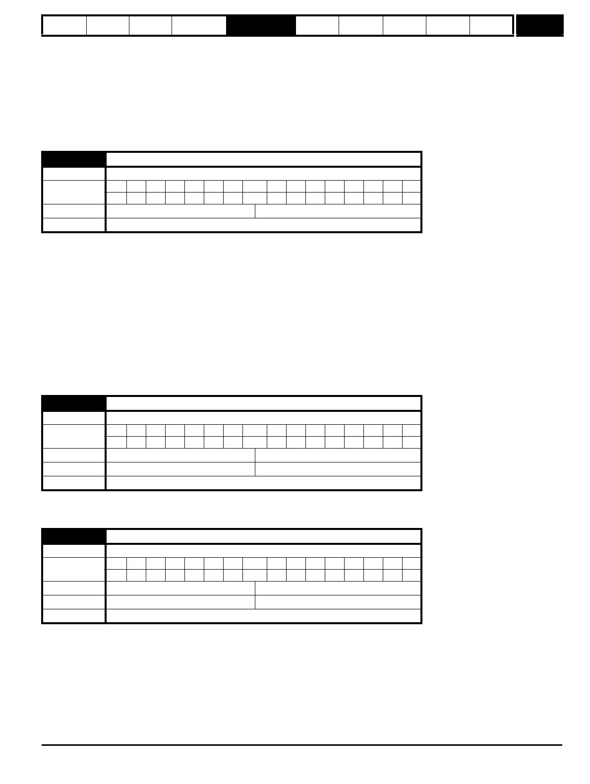
13.11 Absolute mode enable
Drive modes Open-loop, Closed-loop vector, Servo
Coding
Bit SP FI DE Txt VM DP ND RA NC NV PT US RW BU PS
111
Default Open-loop, Closed-loop vector, Servo 0
Update rate Background read
13.12 Position controller speed clamp
Drive modes Open-loop, Closed-loop vector, Servo
Coding
Bit SP FI DE Txt VM DP ND RA NC NV PT US RW BU PS
111
Range Open-loop, Closed-loop vector, Servo 0 to 250 rpm
Default Open-loop, Closed-loop vector, Servo 150
Update rate Background read
13.13 Orientation position reference
Drive modes Closed-loop vector, Servo
Coding
Bit SP FI DE Txt VM DP ND RA NC NV PT US RW BU PS
111
Range Closed-loop vector, Servo 0 to 65,535
Default Closed-loop vector, Servo 0
Update rate Background read

 Loading...


