Menu 12
Parameter
structure
Keypad and
display
Parameter
x.00
Parameter
description format
Advanced parameter
descriptions
Macros
Serial comms
protocol
Electronic
nameplate
Performance RFC mode
230 Unidrive SP Advanced User Guide
www.controltechniques.com Issue Number: 10
If the current magnitude falls below the lower current threshold the brake is applied immediately. The lower threshold should be set to the required
level to detect the condition where the motor has been disconnected from the drive. If this parameter is set to zero the loss of current will not cause
the brake to be applied. However, the flux detection and current threshold latch will be reset when the drive is disabled.
When stopping, the drive reference can be removed (i.e. Pr 1.11 = 0), but the brake will remain energized (open) until the motor has remained at a
speed below the brake apply speed for the delay defined by Pr 12.46. The delay prevents rapid activation and de-activation of the brake when fine
control of a motor is required close to zero speed.
See Pr 12.45.
The post-brake release time is used to allow for the brake release time. From the time that the drive is enabled and then during this period the speed
reference is held constant at zero, so that there is no sudden increase in motor speed when the brake actually releases.
The brake apply delay is used to allow for the brake application time. During this period the Hold zero speed parameter (Pr 6.08) is one, and so the
drive is enabled with zero speed reference. This ensures that the motor remains stationary while the brake is being applied.
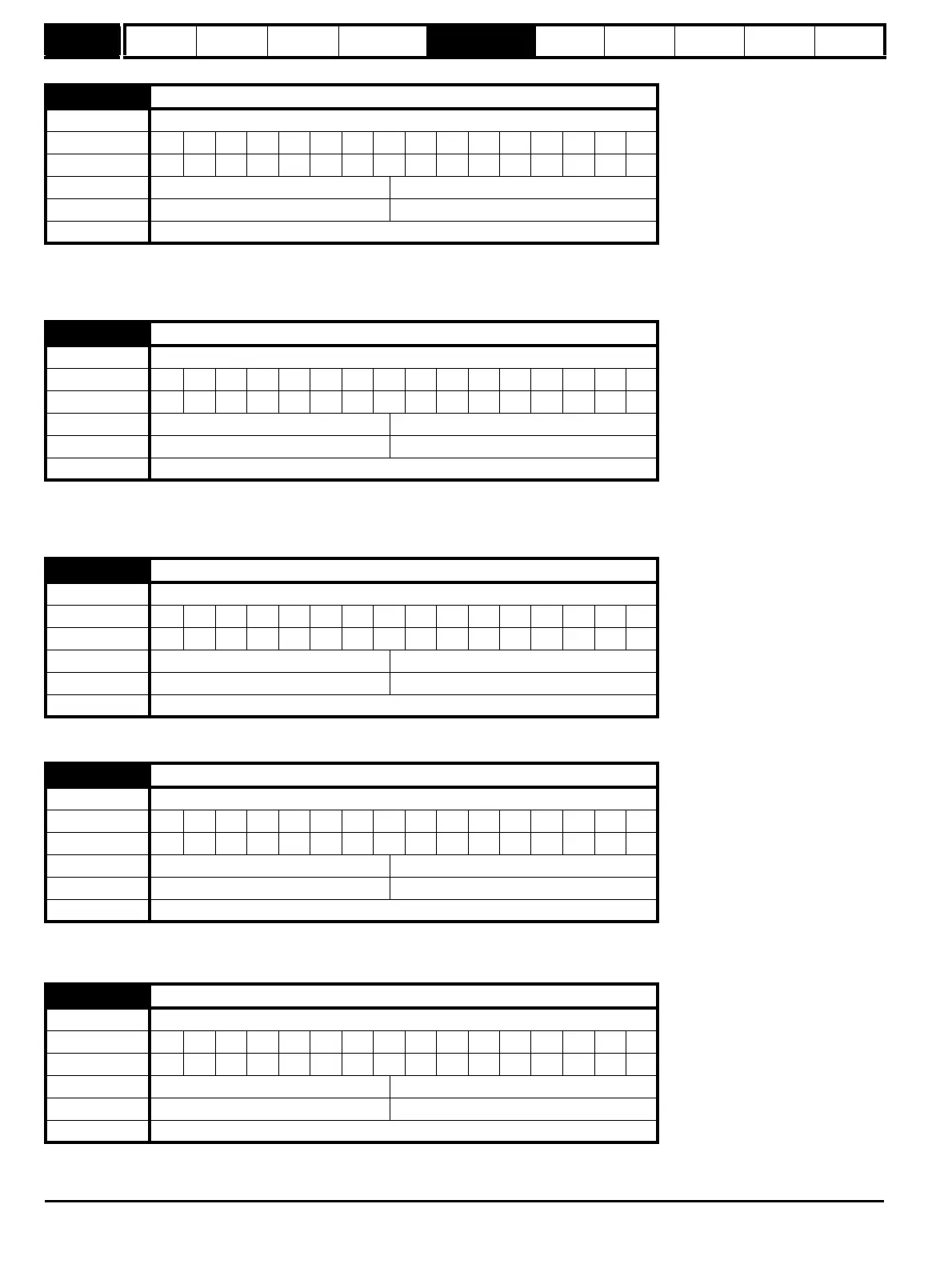
12.43
Low current threshold
Drive modes Open-loop, Closed-loop vector, Servo
Coding Bit SP FI DE Txt VM DP ND RA NC NV PT US RW BU PS
111
Range Open-loop, Closed-loop vector, Servo 0 to 200 %
Default Open-loop, Closed-loop vector, Servo 10
Update rate Background read
12.45
Brake apply speed
Drive modes Closed-loop vector, Servo
Coding Bit SP FI DE Txt VM DP ND RA NC NV PT US RW BU PS
111
Range Closed-loop vector, Servo 0 to 200 rpm
Default Closed-loop vector, Servo 5
Update rate Background read
12.46
Brake apply speed delay
Drive modes Closed-loop vector, Servo
Coding Bit SP FI DE Txt VM DP ND RA NC NV PT US RW BU PS
1 111
Range Closed-loop vector, Servo 0.0 to 25.0 s
Default Closed-loop vector, Servo 1.0
Update rate Background read
12.47
Post-brake release delay
Drive modes Closed-loop vector, Servo
Coding Bit SP FI DE Txt VM DP ND RA NC NV PT US RW BU PS
1 111
Range Closed-loop vector, Servo 0.0 to 25.0 s
Default Closed-loop vector, Servo 1.0
Update rate Background read
12.48
Brake-apply delay
Drive modes Closed-loop vector, Servo
Coding Bit SP FI DE Txt VM DP ND RA NC NV PT US RW BU PS
111
Range Closed-loop vector, Servo 0.0 to 25.0 s
Default Closed-loop vector, Servo 1.0
Update rate Background read

 Loading...


