Parameter
structure
Keypad and
display
Parameter x.00
Parameter
description format
Advanced parameter
descriptions
Macros
Serial comms
protocol
Electronic
nameplate
Performance RFC mode
406 Unidrive SP Advanced User Guide
www.controltechniques.com Issue Number: 10
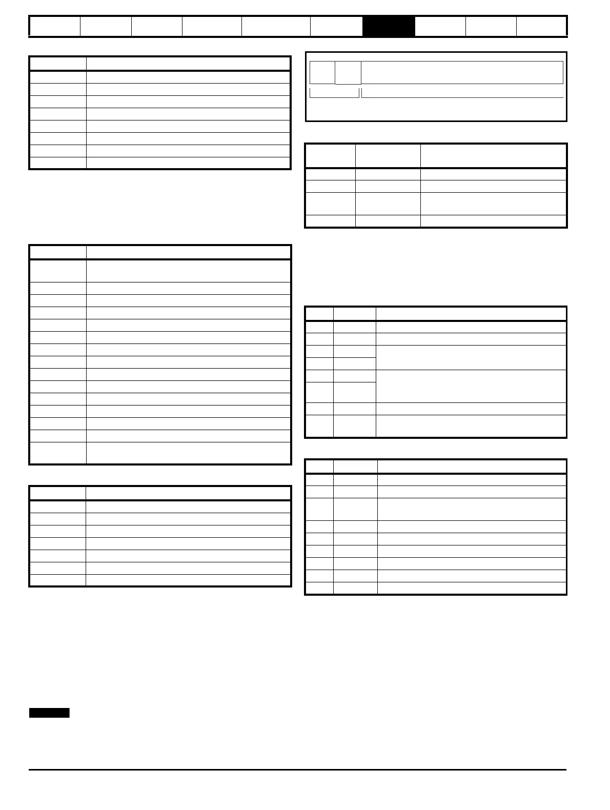
Table 7-6 Slave response
FC23 Read/Write multiple
Writes and reads two contiguous arrays of registers. The slave imposes
an upper limit on the number of registers which can be written. If this is
exceeded the slave will discard the request and the master will time out.
Table 7-7 Master request
Table 7-8 Slave response
7.2.7 Extended data types
Standard MODBUS registers are 16bit and the standard mapping maps
a single #X.Y parameter to a single MODBUS register. To support 32bit
data types (integer and float) the MODBUS multiple read and write
services are used to transfer a contiguous array of 16bit registers.
Slave devices typically contain a mixed set of 16bit and 32bit registers.
To permit the master to select the desired 16bit or 32bit access the top
two bits of the register address are used to indicate the selected data
type.
The selection is applied for the whole block access.
The 2bit type field selects the data type according to the table below:
If a 32bit data type is selected then the slave uses two consecutive 16bit
MODBUS registers (in 'big endian'). The master must also set the
correct 'number of 16bit registers'.
Example, read #20.21 through #20.24 as 32bit parameters using FC03
from node 8:
Table 7-9 Master request
Table 7-10 Slave response
Reads when actual parameter type is different from selected
The slave will send the least significant word of a 32 bit parameter if that
parameter is read as part of a 16 bit access.
The slave will sign extend the least significant word if a 16 bit parameter
is accessed as a 32 bit parameter. The number of 16 bit registers must
be even during a 32 bit access.
Example, If #1.28 is a 32 bit parameter with a value of 0x12345678,
#1.29 is a signed 16 bit parameter with a value of 0xABCD, and #1.30 is
a signed 16 bit parameter with a value of 0x0123.
Byte Description
0 Slave source node address
1 Function code 0x10
2 Start register address MSB
3 Start register address LSB
4 Number of 16bit registers written MSB
5 Number of 16bit registers written LSB
6 CRC LSB
7 CRC MSB
Byte Description
0
Slave node address 1 through 247,
0 is global
1 Function code 0x17
2 Start register address to read MSB
3 Start register address to read LSB
4 Number of 16bit registers to read MSB
5 Number of 16bit registers to read LSB
6 Start register address to write MSB
7 Start register address to write LSB
8 Number of 16bit registers to write MSB
9 Number of 16bit registers to write LSB
10 Length of register data to write (in bytes)
11 Register data 0 MSB
12 Register data 0 LSB
11+byte count CRC LSB
12+byte
count
CRC MSB
Byte Description
0 Slave source node address
1 Function code 0x17
2 Length of register data in read block (in bytes)
3 Register data 0 MSB
4 Register data 0 LSB
3+byte count CRC LSB
4+byte count CRC MSB
Type field
bits 15-14
Selected data
type
Comments
00 INT16 backward compatible
01 INT32
10 Float32
IEEE754 standard
Not supported on all slaves
11 Reserved
Byte Value Description
0 0x08 Slave destination node address
1 0x03 FC03 multiple read
20x47
Start register address #20.21
(16384 + 2021 - 1) = 18404 = 0x47E4
30xE4
4 0x00 Number of 16bit registers to read
#20.21 through #20.24 is 4x32bit registers =
8x16bit registers
50x08
6 CRC LSB
7
CRC
MSB
Byte Value Description
0 0x08 Slave destination node address
1 0x03 FC03 multiple read
20x10
Length of data (bytes) = 4x32bit registers =
16bytes
3-6 #20.21 data
7-10 #20.22 data
11-14 #20.23 data
15-18 #20.24 data
19 CRC LSB
20 CRC MSB
bit 15
TYP1
bits 0 - 13
Type select Parameter address
X x 100+Y-1
bit 14
TYP0