EasyManua.ls Logo

Emerson unidrive sp User Manual

Emerson unidrive sp
420 pages
To Next Page IconTo Next Page
To Previous Page IconTo Previous Page
Page #80 background imageLoading...
Page #80 background image
Menu 3
All modes
Parameter
structure
Keypad and
display
Parameter
x.00
Parameter
description format
Advanced parameter
descriptions
Macros
Serial comms
protocol
Electronic
nameplate
Performance RFC mode
80 Unidrive SP Advanced User Guide
www.controltechniques.com Issue Number: 10
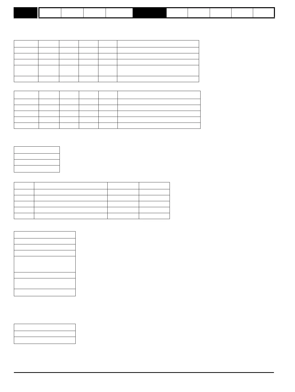
Example of Hiperface transfer: Delete data field
Transfer the "delete data field" message to the encoder comms buffer by writing the sequence of words shown in the table below to Pr 90.22. A check
should be carried out before each word is written to ensure that the parameter is zero (i.e. the drive has taken any previous data).
The response from the encoder is a follows.
SC.EnDat
The Heidenhain EnDat protocol is a synchronous protocol using the following command message format (drive to encoder).
The following commands are supported:
The following is an example of the response when the Encoder to send position command is used (encoder to drive).
The example shown above is for an encoder with 12 bits representing the turns and 13 bits representing the position within a turn. The position
command only requires one byte to be sent to the encoder. Bits 14 and 13 can both be set in the transmit register if required to indicate that this is
both the first and last byte of the message.
If any other command is used then the response is as follows (encoder to drive).
Example of EnDat transfer: Read position
Disable drive encoder position check by setting Pr 90.21 to one. This should be set back to zero at the end of the transfer if encoder position checking
is required.
Bit 15 Bit 14 Bit 13 Data
0xa0ff 1 0 1 0xff Broadcast message so address = 0xff
0x804d 1 0 0 0x4d Create data field command
0x8002 1 0 0 0x02 Data field 2
0x8065 1 0 0 0x65
Status of data existing data field 2 with bit 7
set to zero
0x8055 1 1 0 0x55 Code for data field at default of 0x55
Bit 15 Bit 14 Bit 13 Data
0x8040 1 0 0 0x40 Encoder address
0x8042 1 0 0 0x4d Create data field command
0x8003 1 0 0 0x02 Data field 2
0x8059 1 0 0 0x65 Status of the data field before delete
0x8063 1 1 0 0x78 Checksum
Command
1
st
byte
Address
Data (LSB)
Data (MSB)
4
th
byte
Code Command Address Data
0x00 Encoder to send position Don’t care Don’t care
0x01 Selection of memory area MRS code Don’t care
0x03 Encoder to receive parameter Address Data
0x04 Encoder to send parameter Address Don’t care
0x05 Encoder to receive reset Don’t care Don’t care
LS byte
1
st
byte
Bits 7-0 = 0
Bits 7-0 = 0
Bits 7-0 = 0
Bits 7-0 = 0
Bits 5-0 = 0
Bit 6 = Alarm bit
Bit 7 = Bit 0 of position
Bits 7-0 = Bits 8-1 of position
Bits 3-0 = Bits 12-9 of position
Bits 7-4 = Bits 3-0 of turns
MS byte
8
th
byte
Bits 7-0 = Bits 11-4 of turns
Address
1
st
byte
Data (LSB)
Data (MSB)
3
rd
byte

Table of Contents

Question and Answer IconNeed help?

Do you have a question about the Emerson unidrive sp and is the answer not in the manual?

Emerson unidrive sp Specifications

General IconGeneral
TypeAC Drive
Storage Temperature-40°C to +70°C
Communication OptionsCANopen, Ethernet, Profibus, DeviceNet
Safety FeaturesSafe Torque Off (STO), Safe Stop 1 (SS1), Safe Operating Stop (SOS)
Overload150% for 60 seconds
EnclosureIP20
Output Voltage Range0 - Input Voltage
Protection FeaturesOvercurrent, Overvoltage, Undervoltage, Short Circuit
Humidity95% non-condensing
Cooling MethodFan cooled
DimensionsVaries depending on the power rating and enclosure type
WeightVaries depending on the power rating and enclosure type
Input Voltage200 VAC - 690 VAC ±10%

Summary

Parameter structure

1.1 Menu 0

Describes Menu 0, its fixed and programmable parameters, and its relation to other menus.

1.2 Advanced menus

Explains the purpose and accessibility of advanced menus for specific drive features.

Keypad and display

2.1 Understanding the display

Explains the SM-Keypad and SM-Keypad Plus displays, including their features and layout.

2.2 Keypad operation

Details the operation of the keypad controls, including the joypad, mode, and control buttons.

2.4 Parameter view mode

Explains navigation between parameters and menus, and displaying parameter values.

2.5 Edit mode

Details how to enter Edit Mode and modify parameter values using the keypad, including digit selection.

Parameter x.00

3.2 Saving parameters in drive EEPROM

Details the process of saving parameters to EEPROM using Pr x.00, emphasizing data loss risk and features.

3.3 Loading defaults

Explains how to load default drive parameters, including the implications for user-saved parameters.

3.4 SMARTCARD transfers

Describes transferring parameters, setup macros, and ladder programs to/from SMARTCARDs.

Parameter description format

4.1 Parameter ranges and variable maximums:

Defines parameter ranges and variable maximums, which can depend on other parameters, drive rating, or drive mode.

Advanced parameter descriptions

5.2 Feature look-up table

Presents a comprehensive table linking features to their corresponding parameter numbers for easy reference.

Menu 1: Frequency/speed reference

1.06 Maximum reference clamp

Defines the maximum speed (closed-loop mode) or frequency (open-loop mode) reference.

1.10 Bipolar reference enable

Enables or disables bipolar reference, affecting how the reference value is interpreted.

1.15 Preset selector

Defines how preset references are selected based on digital inputs and the value of Pr 1.50.

1.07 Minimum reference clamp

Sets the minimum speed or frequency reference, with effects of negative minimum clamp enable.

1.16 Preset reference selector timer

Defines the time between preset reference changes when Pr 1.15 is set to 9.

1.08 Negative minimum reference clamp enable

Enables or disables the negative minimum reference clamp, affecting the minimum speed reference.

1.17 Keypad control mode reference

Defines the frequency/speed reference when keypad control mode is active.

1.09 Reference offset select

Selects how the reference offset is applied, either by scaling or by adding the offset value.

1.18 Precision reference coarse

Defines the coarse part of the reference for precision control.

1.14 Reference selector

Defines how the reference is selected, allowing choices from analog inputs, preset speeds, or keypad references.

1.19 Precision reference fine

Defines the fine part of the reference for precision control, improving resolution.

Menu 2: Ramps

2.01 Post ramp reference

Defines the post-ramp reference, which is the output after the ramp block.

2.06 S ramp enable

Enables the S-Ramp function, used for smoother acceleration/deceleration curves.

2.02 Ramp enable

Enables or disables the ramp function, controlling acceleration and deceleration ramps.

2.07 S ramp acceleration limit

Defines the maximum rate of change of acceleration/deceleration for the S-Ramp function.

2.03 Ramp hold

Holds the ramp output constant, disabling ramp function when a drive stop is demanded.

2.08 Standard ramp voltage

Sets the voltage level for standard ramp mode, affecting motor deceleration.

2.04 Ramp mode select

Selects the ramp mode, including fast ramp, standard ramp, and standard ramp with voltage boost.

Menu 3: Slave frequency, speed feedback, speed control and regen operation

Parameter descriptions: Closed-loop vector and Servo

3.10 Speed controller proportional gain (Kp1)

Sets the proportional gain for the speed controller, affecting its response to errors.

3.11 Speed controller integral gain (Ki1)

Sets the integral gain for the speed controller, affecting its ability to eliminate steady-state errors.

3.17 Speed controller set-up method

Selects the method for setting up speed controller gains, including auto-tune options.

3.18 Motor and load inertia

Defines the motor and load inertia, used for calculating speed controller gains and torque feed-forwards.

3.41 Drive encoder auto configuration enable / SSI binary format select

Enables automatic encoder configuration and selects SSI binary format.

Menu 4: Torque and current control

5.6.1 Open-loop

Describes operation in stator flux reference frame under steady state conditions, including current limits.

5.6.2 Closed-loop vector

Explains operation in the rotor flux reference frame, controlled by current limits.

5.6.3 Servo

Details operation in the rotor flux reference frame for servo motors, controlled by current limits.

5.6.4 Regen

Describes operation in a reference frame aligned to drive terminal voltage for regen mode.

5.6.5 Parameter descriptions: Open-loop

Provides detailed descriptions of parameters relevant to the open-loop torque and current control.

5.6.5 Parameter descriptions: Closed-loop vector

Details parameters relevant to closed-loop vector torque and current control.

Menu 5: Motor control

Open loop

Explains the open-loop motor control logic, including reference selection and ramp functions.

Closed-loop vector and Servo

Describes the logic diagram for closed-loop vector and servo motor control, including flux calculator and current control.

Regen

Explains the logic diagram for Regen mode, covering supply synchronization, current control, and output parameters.

5.12 Autotune

Initiates auto-tune tests to measure motor parameters and set controller gains.

Macros

6.2 Macro 1 - Easy Mode

Describes the Easy Mode macro for simplest drive operation, identical to default except for fewer parameters in Menu 0.

Serial communications protocol

7.2 CT Modbus RTU specification

Details the adaptation of the Modbus RTU protocol for Control Techniques products, including frame format and register mapping.

Rotor Flux Control (RFC) mode

10.2 Setting up the RFC mode

Provides step-by-step instructions on setting up the drive to run in RFC mode, including recommended switching frequency.

Related product manuals