Parameter
structure
Keypad and
display
Parameter
x.00
Parameter
description format
Advanced parameter
descriptions
Macros
Serial comms
protocol
Electronic
nameplate
Performance RFC mode
Menus 15 to 17
SM-I/O Lt Tmr
Unidrive SP Advanced User Guide 299
Issue Number: 10 www.controltechniques.com
The menu for the relevant slot appears for the new Solutions Module category with the default parameter values for the new category.
When no Solutions Module is installed in the relevant slot this parameter is zero. When a Solutions Module is installed this parameter displays the
identification code.
203: SM-I/O Timer
207: SM-I/O Lite
The new parameter values are not stored in the drive EEPROM until the user performs a parameter save by setting Pr xx.00 to 1000 and pressing the
stop/reset button. When parameters are saved by the user in the drive EEPROM, the option code of the currently installed Solutions Module is saved
in the drive EEPROM. If the drive is subsequently powered-up with a different Solutions Module installed, or no Solutions Module is installed when
one was previously installed, the drive will trip on SLx.dF or SLx.nF.
This parameter shows the version of software programmed into the Solutions Module. The software sub version is displayed in Pr x.51.
These two parameters display the software version in the form of:
Pr x.02 = xx.yy
Pr x.51 = zz
If the Solutions Module analog input is programmed in any of the modes 2 to 5 (see Pr x.38 on page 302) then this bit is set if the current input falls
below 3mA. This bit can be designated to a digital output to indicate that the current input is less than 3mA.
0: OFF inactive
1: On active
Terminals T5 to T7 are three programmable digital inputs.
These parameters indicate the state of the digital input terminals.
If an external trip is required, then one of the terminals should be programmed to control the external trip parameter (Pr 10.32), with the invert set to a
On so that the terminal must be made active for the drive not to trip.
The digital inputs are set-up in positive logic only. This logic cannot be changed.
0: OFF de-energized
1: On energized
This parameter indicates the state of the relay.
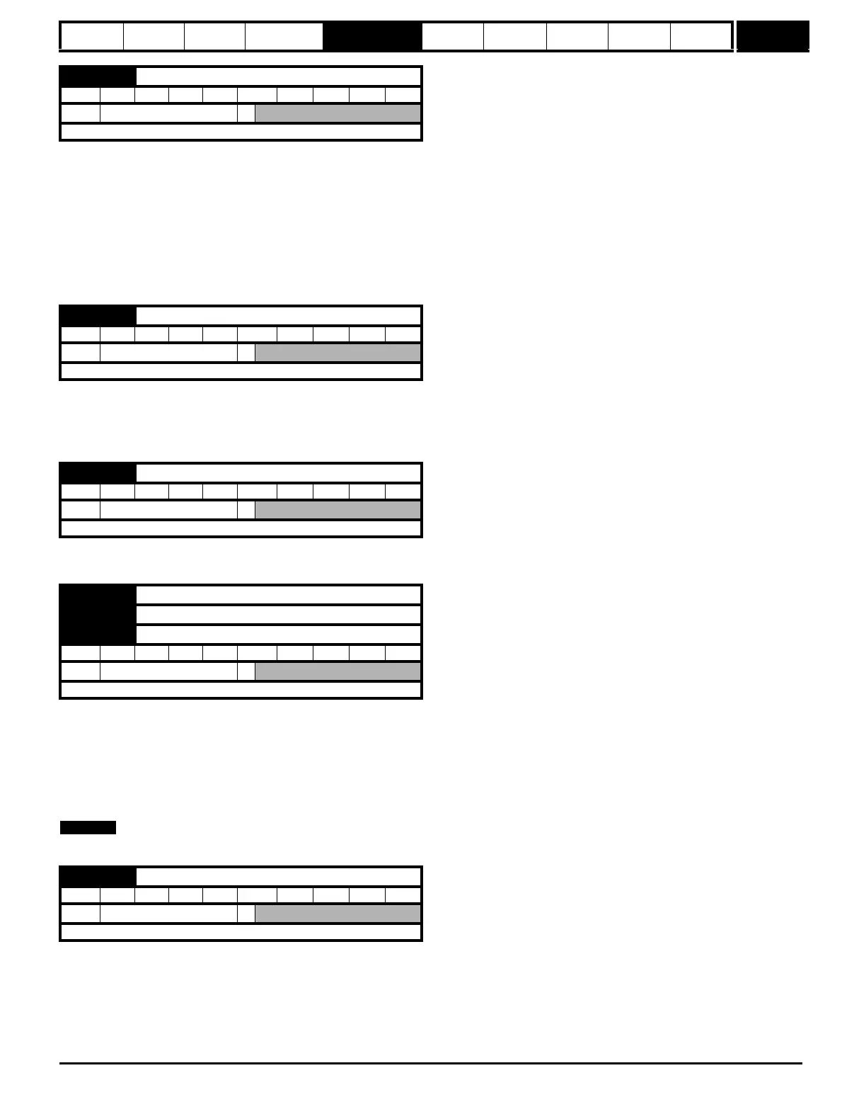
x.01 Solutions Module ID code
RO Uni PT US
Ú
0 to 599
Ö
Update rate: Write on power-up
x.02 Solutions Module software version
RO Uni NC PT
Ú
00.00 to 99.99
Ö
Update rate: Write on power-up
x.03 Current loop loss indicator
RO Bit NC PT
Ú
OFF(0) or On(1)
Ö
Update rate: Background write
x.04 Terminal T5 digital input 1 state
x.05 Terminal T6 digital input 2 state
x.06 Terminal T7 digital input 3 state
RO Bit NC PT
Ú
OFF(0) or On(1)
Ö
Update rate: Background write
x.07 Relay state (Terminals T21 and T23)
RO Bit NC PT
Ú
OFF(0) or On(1)
Ö
Update rate: Background write

 Loading...


