Menu 3
All modes
Parameter
structure
Keypad and
display
Parameter
x.00
Parameter
description format
Advanced parameter
descriptions
Macros
Serial comms
protocol
Electronic
nameplate
Performance RFC mode
78 Unidrive SP Advanced User Guide
www.controltechniques.com Issue Number: 10
At power-up Pr 3.48 is initially zero, but is set to one when the drive encoder and any encoders connected to position category modules have been
initialized. The drive cannot be enabled until this parameter is one.
If any trips occur that could indicate that the encoder system is no longer initialized correctly (i.e. Enc2-Enc8 and Enc11-Enc17), or the internal 24V or
encoder power supplies are overloaded (i.e. Enc1 or PS.24V), Pr 3.48 is set to zero and the drive cannot be enabled until the encoder is re-initialized.
It is likely that the failure of either of these supplies will cause one of the other encoder trips and it should be noted that Enc1 or PS.24V trips can
override Enc2-Enc8 and Enc11-Enc17 trips so that the power supply overload is not mistaken for an encoder error.
When this parameter is set to one, additional information for the motor object can be transferred from Pr 18.11 to Pr 18.17 as shown below.
If Pr 3.50 is set to one Pr 3.28, Pr 3.29 and Pr 3.30 are not updated. If this parameter is set to zero these parameters are updated normally.
5.5.1 Communication with Hiperface and EnDat encoders
It is possible to use the communications channel between the drive and a Hiperface or EnDat encoder. This allows access to the encoder functions
including reading the encoder position and, reading and writing to encoder memory. The system can be used to communicate with SC.Hiper and
SC.EnDat type encoders provided that the position checking system has been disabled, by setting Pr 90.21 to one.
To send a message to the encoder the required message must be written to the transmit register (Pr 90.22). To read the response from the encoder
the data is read from the receive register (Pr 90.23).
Bits 13-15 of the registers are used to indicate the following:
Data should be written to the transmit register (Pr 90.22) when the register has been reset to zero by the drive. The data will be transferred to the
comms buffer and the transmit register will be cleared.
Data can be read from the receive register (Pr 90.23) at any time. If there is receive data in the buffer bit 15 will be set. Once the data has been read
the register should be cleared and the drive will then transfer more data.
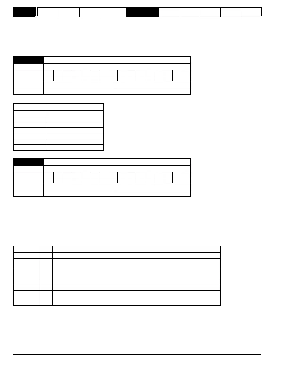
3.49 Full motor object electronic nameplate transfer
Drive modes Open-loop, Closed-loop vector, Servo
Coding
Bit SP FI DE Txt VM DP ND RA NC NV PT US RW BU PS
111
Default Open-loop, Closed-loop vector, Servo 0
Update rate Read on reset
User parameter Motor object parameter
Pr 18.11 Motor object version number
Pr 18.12 Motor type (MSW)
Pr 18.13 Motor type (LSW)
Pr 18.14 Motor manufacturer
Pr 18.15 Motor serial number (MSW)
Pr 18.16 Motor serial number
Pr 18.17 Motor serial number (LSW)
3.50 Position feedback lock
Drive modes Open-loop, Closed-loop vector, Servo
Coding
Bit SP FI DE Txt VM DP ND RA NC NV PT US RW BU PS
111
Default Open-loop, Closed-loop vector, Servo 0
Update rate 4ms read
Register Bit Function
Transmit 15 Must be set for the drive to transfer the LS byte to the comms buffer.
Transmit 14
The LS byte is the last byte of the message and this byte should be put in the comms buffer and be
transferred to the encoder.
Transmit 13
The LS byte is the first byte of the message. (If this is used the buffer pointer is reset to the start of
the buffer).
Receive 15 Indicates data from the last transfer can be read from the receive buffer.
Receive 14 The byte in the LS byte is the last byte of the receive message
Receive 13
There is no data in the receive buffer and the LS byte is the comms system status. If there was an
error in the received message this will always be set and one of the status error bits will be set until
the comms is used again by this system or by the drive.