Parameter
structure
Keypad and
display
Parameter
x.00
Parameter
description format
Advanced parameter
descriptions
Macros
Serial comms
protocol
Electronic
nameplate
Performance RFC mode
Menu 12
Unidrive SP Advanced User Guide 227
Issue Number: 10 www.controltechniques.com
The current magnitude is compared to an upper and lower threshold by a comparator with hysteresis to give torque present and drive output open
detection functions respectively. The upper and lower threshold currents are given as a percentage of motor current defined by Pr 5.07 (or Pr 21.07 if
motor map 2 is selected). The upper threshold should be set to the current level that indicates that there is magnetizing current and sufficient torque
producing current in the motor to deliver the required amount of torque when the brake is released. The output of the comparator remains active after
this level has been reached unless the current subsequently falls below the lower threshold which should be set to the required level to detect the
condition where the motor has been disconnected from the drive. If the lower threshold is set greater or equal to the upper threshold, the upper
threshold applies with a hysteresis band of zero. If Pr 12.42 and Pr 12.43 are both set to zero then the output of the comparator is always one.
The frequency comparator can be used to detect when the motor frequency has reached a level where the motor can produce the required amount of
torque to ensure that the motor rotates in the demanded direction when the brake is released. This parameter should be set to a level slightly above
the motor slip frequency that is likely to occur under the highest expected load that is applied to the motor when the brake is released.
The brake apply frequency threshold is used to ensure that the brake is applied before the motor frequency reaches zero and to prevent the motor
rotating (in the reverse direction due to an overhauling load for example) during the brake apply time. If the frequency falls below this threshold, but
the motor is not required to stop (i.e. reversing direction without stopping), provided the Reference on parameter (Pr 1.11) remains at one, the brake
is not applied. This prevents the brake from activating and de-activating as the motor passes through zero speed.
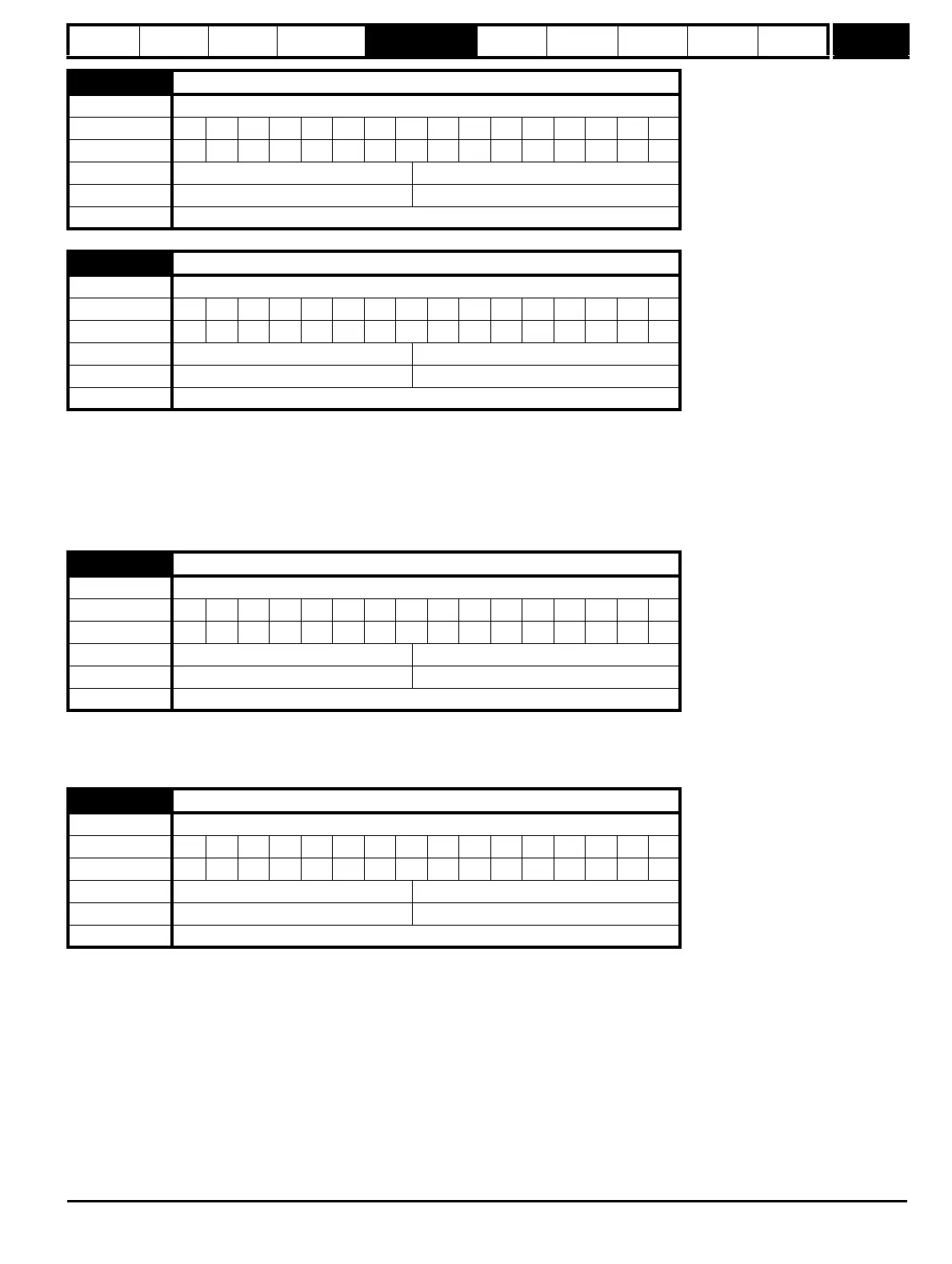
12.42
Upper current threshold
Drive modes Open-loop
Coding Bit SP FI DE Txt VM DP ND RA NC NV PT US RW BU PS
111
Range Open-loop 0 to 200 %
Default Open-loop 50
Update rate Background read
12.43
Lower current threshold
Drive modes Open-loop
Coding Bit SP FI DE Txt VM DP ND RA NC NV PT US RW BU PS
111
Range Open-loop 0 to 200 %
Default Open-loop 10
Update rate Background read
12.44
Brake release frequency
Drive modes Open-loop
Coding Bit SP FI DE Txt VM DP ND RA NC NV PT US RW BU PS
1 111
Range Open-loop 0.0 to 20.0 Hz
Default Open-loop 1.0
Update rate Background read
12.45
Brake apply frequency
Drive modes Open-loop
Coding Bit SP FI DE Txt VM DP ND RA NC NV PT US RW BU PS
1 111
Range Open-loop 0.0 to 20.0 Hz
Default Open-loop 2.0
Update rate Background read

 Loading...


