Menu 5
Parameter
structure
Keypad and
display
Parameter
x.00
Parameter
description format
Advanced parameter
descriptions
Macros
Serial comms
protocol
Electronic
nameplate
Performance RFC mode
124 Unidrive SP Advanced User Guide
www.controltechniques.com Issue Number: 10
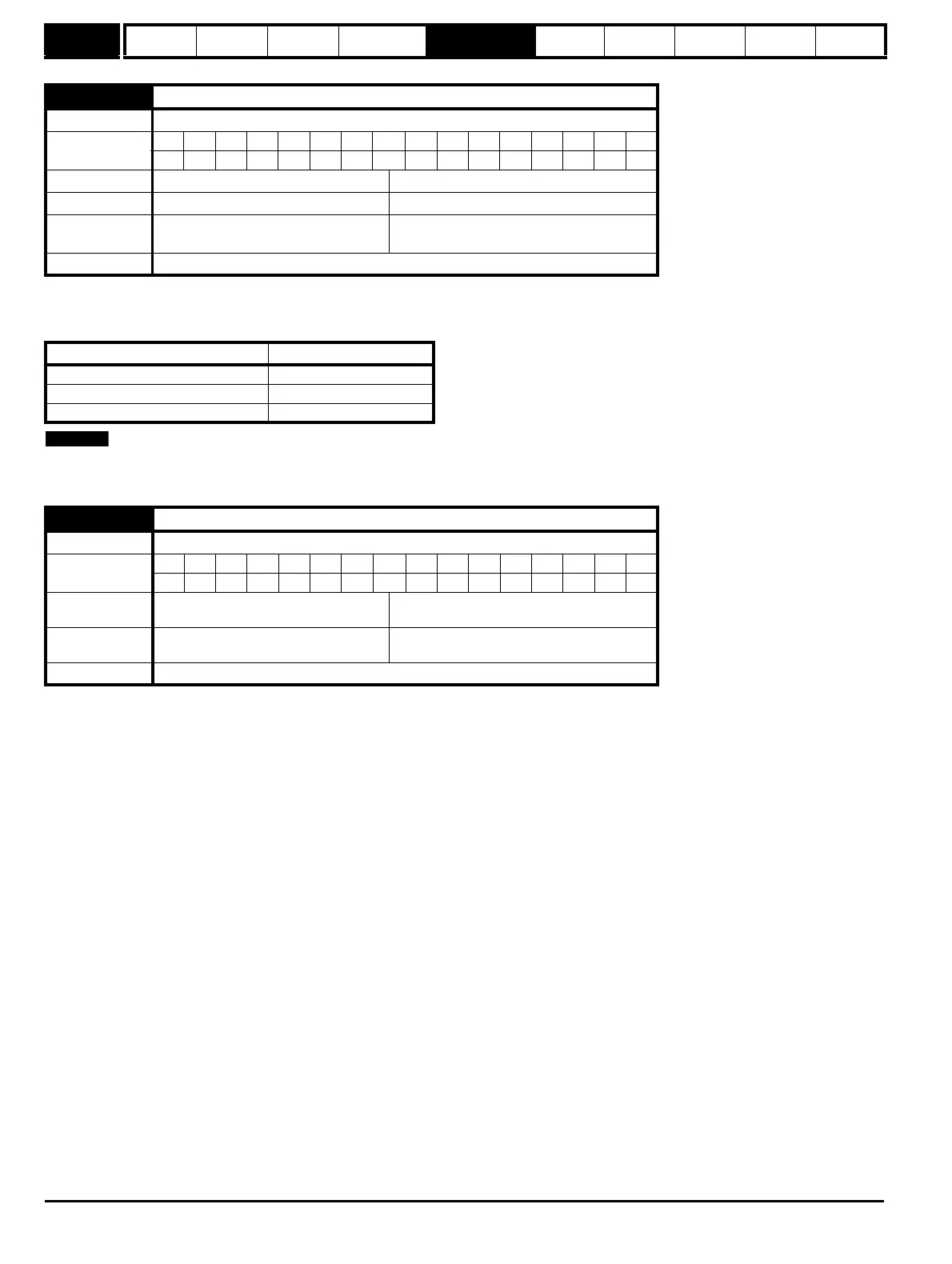
Pr 5.17 shows the stator resistance of the motor. The units vary with the drive size to ensure that the full range of likely resistances can be
represented with suitable resolution. The table below shows the units. Therefore 1.000 in the parameter represents the resistance shown in the units
column.
From software version 1.07.00 onwards the maximum value of this parameter increased from 30 to 65 ohms to allow use of the autotune with very
small motors. rS trips will be seen with small motors with a higher resistance than 30 ohms per phase with earlier software versions.
*The maximum switching frequency available is limited for some drive sizes as shown in the table below.
5.17 Stator resistance
Drive modes Open-loop, Closed-loop vector, Servo
Coding
Bit SP FI DE Txt VM DP ND RA NC NV PT US RW BU PS
3 1 111
Range Open-loop, Closed-loop vector, Servo 0.000 to 65.000
Default Open-loop, Closed-loop vector, Servo 0.000
Second motor
parameter
Open-loop, Closed-loop vector, Servo Pr 21.12
Update rate Background read
Drive size Units
SP0xxx 10 Ohms
SP1xxx to SP5xxx 1 Ohm
SP6xxx toSP9xxx and SPMxxxxx 0.01 Ohms
5.18 Maximum switching frequency
Drive modes Open-loop, Closed-loop vector, Servo, Regen
Coding
Bit SP FI DE Txt VM DP ND RA NC NV PT US RW BU PS
1 1 111
Range
Open-loop, Closed-loop vector, Servo,
Regen
0 to 5 (3, 4, 6, 8, 12, 16 kHz)*
Default
Open-loop, Closed-loop vector, Regen
Servo
0 (3 kHz)
2 (6 kHz)
Update rate Background read

 Loading...


