Menu 13
Parameter
structure
Keypad and
display
Parameter
x.00
Parameter
description format
Advanced parameter
descriptions
Macros
Serial comms
protocol
Electronic
nameplate
Performance RFC mode
238 Unidrive SP Advanced User Guide
www.controltechniques.com Issue Number: 10
For normal position control the position changes from the reference and the feedback are accumulated in an integrator during each sample. The
integrator is large enough to guarantee that the position controller will operate with a position error within the range -32,768 revolutions to +32,767
revolutions before rolling over. The position error is displayed in Pr 13.01, Pr 13.02 and Pr 13.03. Pr 13.01 shows the turns error, Pr 13.02 shows the
error within a revolution in 1/2
16
counts per revolution units and Pr 13.03 shows the fine position error in 1/2
32
counts per revolution units. These
values are both positive and negative and so they can be used to show the following error with different levels of resolution.
For orientation mode the error between the orientation position and the position feedback source is shown in Pr 13.02.
The reference and feedback positions can be taken from the drive encoder or a position feedback Solutions Module in one of the Solutions Module
slots. The reference can also be taken from the local reference parameters. If the reference and feedback sources are the same the position
controller cannot be enabled. If a Solutions Module slot is selected as a source, but the module is not a position feedback category Solutions Module
the position controller cannot be enabled. Orientation mode can always be enabled in closed-loop modes.
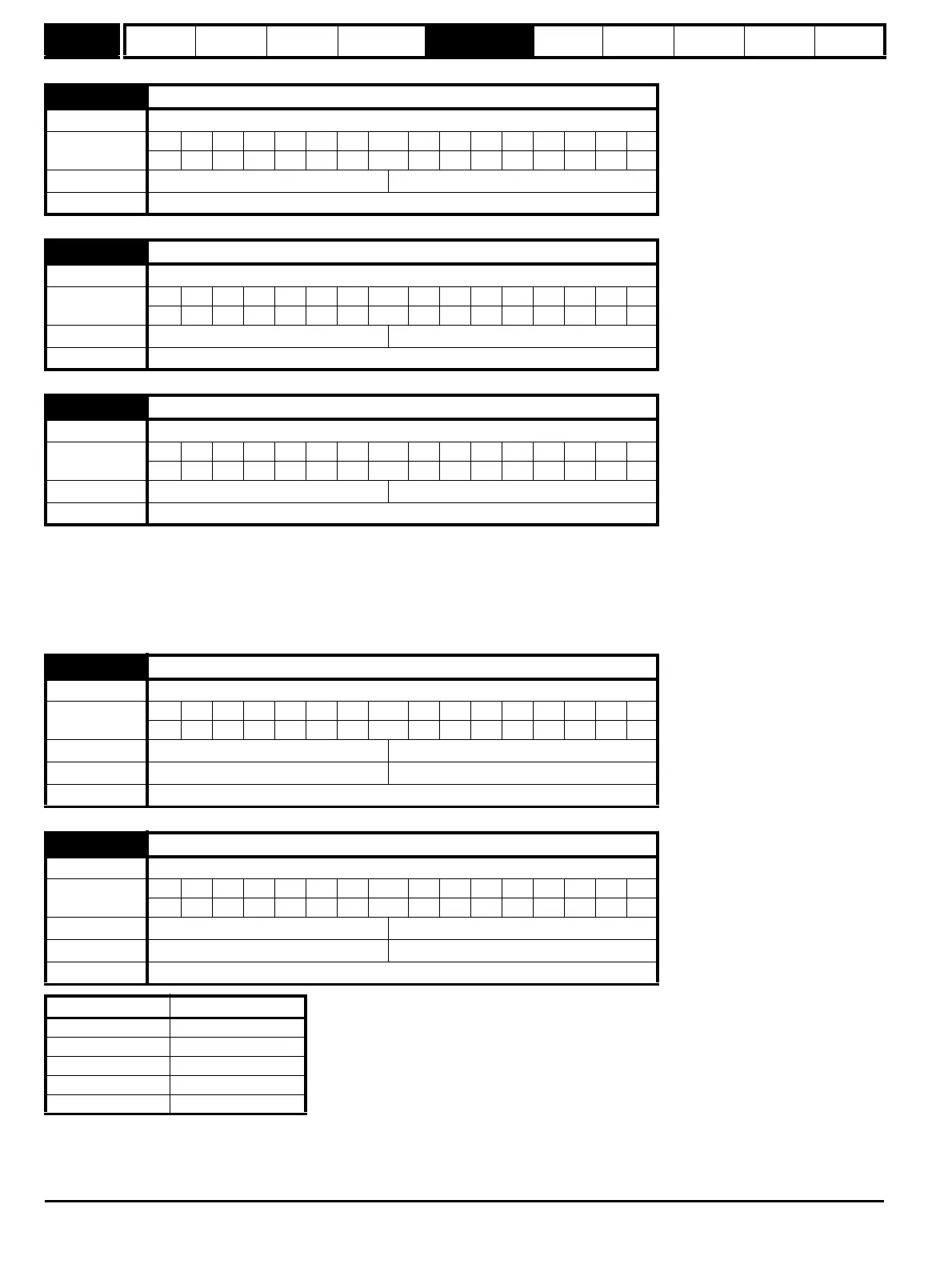
13.01 Revolutions error
Drive modes Open-loop, Closed-loop vector, Servo
Coding
Bit SP FI DE Txt VM DP ND RA NC NV PT US RW BU PS
111
Range Open-loop, Closed-loop vector, Servo -32,768 to 32,767
Update rate 4ms write
13.02 Position error
Drive modes Open-loop, Closed-loop vector, Servo
Coding
Bit SP FI DE Txt VM DP ND RA NC NV PT US RW BU PS
111
Range Open-loop, Closed-loop vector, Servo -32,768 to 32,767
Update rate 4ms write
13.03 Fine position error
Drive modes Open-loop, Closed-loop vector, Servo
Coding
Bit SP FI DE Txt VM DP ND RA NC NV PT US RW BU PS
111
Range Open-loop, Closed-loop vector, Servo -32,768 to 32,767
Update rate 4ms write
13.04 Position controller reference source
Drive modes Open-loop, Closed-loop vector, Servo
Coding
Bit SP FI DE Txt VM DP ND RA NC NV PT US RW BU PS
1 111
Range Open-loop, Closed-loop vector, Servo 0 to 4
Default Open-loop, Closed-loop vector, Servo 0
Update rate Background read
13.05 Position controller feedback source
Drive modes Open-loop, Closed-loop vector, Servo
Coding
Bit SP FI DE Txt VM DP ND RA NC NV PT US RW BU PS
1 111
Range Open-loop, Closed-loop vector, Servo 0 to 3
Default Open-loop, Closed-loop vector, Servo 0
Update rate Background read
Source parameter Source
0 (drv) Drive encoder
1 (slot1) Slot 1
2 (slot2) Slot 2
3 (slot3) Slot 3
4 (locAl) Local reference

 Loading...


