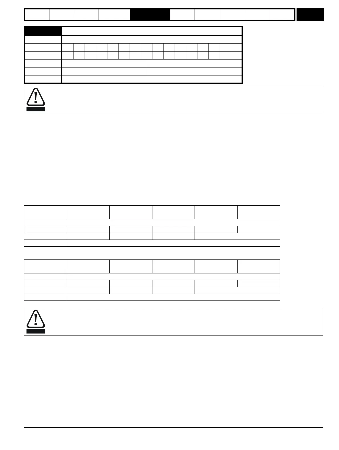
Parameter
structure
Keypad and
display
Parameter
x.00
Parameter
description format
Advanced parameter
descriptions
Macros
Serial comms
protocol
Electronic
nameplate
Performance RFC mode
Menu 12
Unidrive SP Advanced User Guide 225
Issue Number: 10 www.controltechniques.com
0 = dis
The brake controller is disabled and no other drive parameters are affected by the brake controller. When this parameter is changed from a non-zero
value to zero the following parameters are set to zero: Pr 2.03 (all modes), Pr 6.08 (Closed-loop vector and Servo modes), Pr 13.04 and Pr 13.10
(Closed-loop vector and Servo modes if Pr 12.49 = 1).
1 = rel
The brake controller is enabled with I/O set up to control the brake via the relay output T41/42. Drive ok is re-routed to digital I/O 2 (T25).
2 = d IO
The brake controller is enabled with I/O set up to control the brake via digital I/O 2 (T25).
3 = User
The brake controller is enabled, but no parameters are set to select the brake output.
The following tables show the automatic parameter changes that occur to set up digital I/O2 (T25) and the relay output (T41/42) after drive reset when
Pr 12.41 has been changed. The changes are done in two stages: the first stage restores the I/O used as defined by the initial setting of Pr 12.41 and
the second stage sets up the I/O as defined by the new setting of Pr 12.41.
Stage 1: Restore I/O
Stage 2: Set-up I/O
12.41
Brake controller enable
Drive modes Open-loop, Closed-loop vector, Servo
Coding Bit SP FI DE Txt VM DP ND RA NC NV PT US RW BU PS
1 111
Range Open-loop, Closed-loop vector, Servo 0 to 3
Default Open-loop, Closed-loop vector, Servo 0
Update rate Read on drive reset
The brake control functions are provided to allow well co-ordinated operation of an external brake with the drive. While both hardware and
software are designed to high standards of quality and robustness, they are not intended for use as safety functions, i.e. where a fault or
failure would result in a risk of injury. In any application where the incorrect operation of the brake release mechanism could result in injury,
independent protection devices of proven integrity must also be incorporated.
Initial setting in
Pr 12.41
Pr 8.12 (Invert)
Pr 8.22 (Source /
destination)
Pr 8.32 (Input/
output)
Pr 8.17 (Invert) Pr 8.27 (Source)
0 No action
10Pr 10.33 00Pr 10.01
20Pr 10.33 0 No action
3 No action
New setting in
Pr 12.41
Pr 8.12 (Invert)
Pr 8.22 (Source /
destination)
Pr 8.32 (Input/
output)
Pr 8.17 (Invert) Pr 8.27 (Source)
0 No action
10Pr 10.01 10Pr 12.40
20Pr 12.40 1 No action
3 No action
The control terminal relay can be selected as an output to release a brake. If a drive is set up in this manner and a drive replacement takes
place, prior to programming the drive on initial power up, the brake may be released.When drive terminals are programmed to non default
settings the result of incorrect or delayed programming must be considered. The use of a Smartcard in boot mode or an SM-Applications
module can ensure drive parameters are immediately programmed to avoid this situation.

 Loading...


