Parameter
structure
Keypad and
display
Parameter
x.00
Parameter
description format
Advanced parameter
descriptions
Macros
Serial comms
protocol
Electronic
nameplate
Performance RFC mode
394 Unidrive SP Advanced User Guide
www.controltechniques.com Issue Number: 10
6.8 Macro 7 - Brake control
It is recommended that the brake control in menu 12 is used instead of Macro 7 - Brake control.
Table 6-14 Macro 7 menu 0 programmable parameters
The brake control functions are provided to allow well co-ordinated operation of an external brake with the drive. While both hardware and
software are designed to high standards of quality and robustness, they are not intended for use as safety functions, i.e. where a fault or
failure would result in a risk of injury. In any application where the incorrect operation of the brake release mechanism could result in injury,
independent protection devices of proven integrity must also be incorporated.
Where a safety hazard may exist the drive alone must not be permitted to release the brake. An independent safety interlock must be
provided to ensure safe operation in the event of drive failure or incorrect operation.
Macro 7 Brake control
The brake control macro configures the drive to apply or release a mechanical brake on a motor in a crane or hoist application. The drive issues a
brake release signal via a digital output when the relevant conditions are met.
Parameter
Range(
Ú) Default(Ö)
Type
OL CL OL VT SV
0.11 Pre-ramp reference {1.03} ±SPEED_FREQ_MAX Hz/rpm
RO Bi NC PT
0.12 Post ramp reference {2.01} ±SPEED_FREQ_MAX Hz/rpm
RO Bi PT
0.13 Active current {4.02} ±DRIVE_CURRENT_MAX A
RO Bi FI NC PT
0.14 Current magnitude {4.01} 0 to DRIVE_CURRENT_MAX A
RO Uni FI NC PT
0.15 Threshold detector 1 output {12.01} OFF (0) or On (1)
RO Bit NC PT
0.16 Drive ok {10.01} OFF (0) or On (1)
RO Bit NC PT
0.17 Zero speed {10.03} OFF (0) or On (1)
RO Bit NC PT
0.18 Logic function 1 output {9.01} OFF (0) or On (1)
RO Bit NC PT
0.19 Threshold detector 1 level {12.04} 0.00 to 100.00 % 0.00 RW Uni US
0.20 Logic function 2 delay {9.19} ±25.0 s 0.0 RW Bi US
0.21 Not used
0.22 Not used
0.23 Not used
0.24 Not used
0.25 Not used
0.26 Not used
0.27 Not used
0.28 Not used
0.29 Not used
0.30 Not used
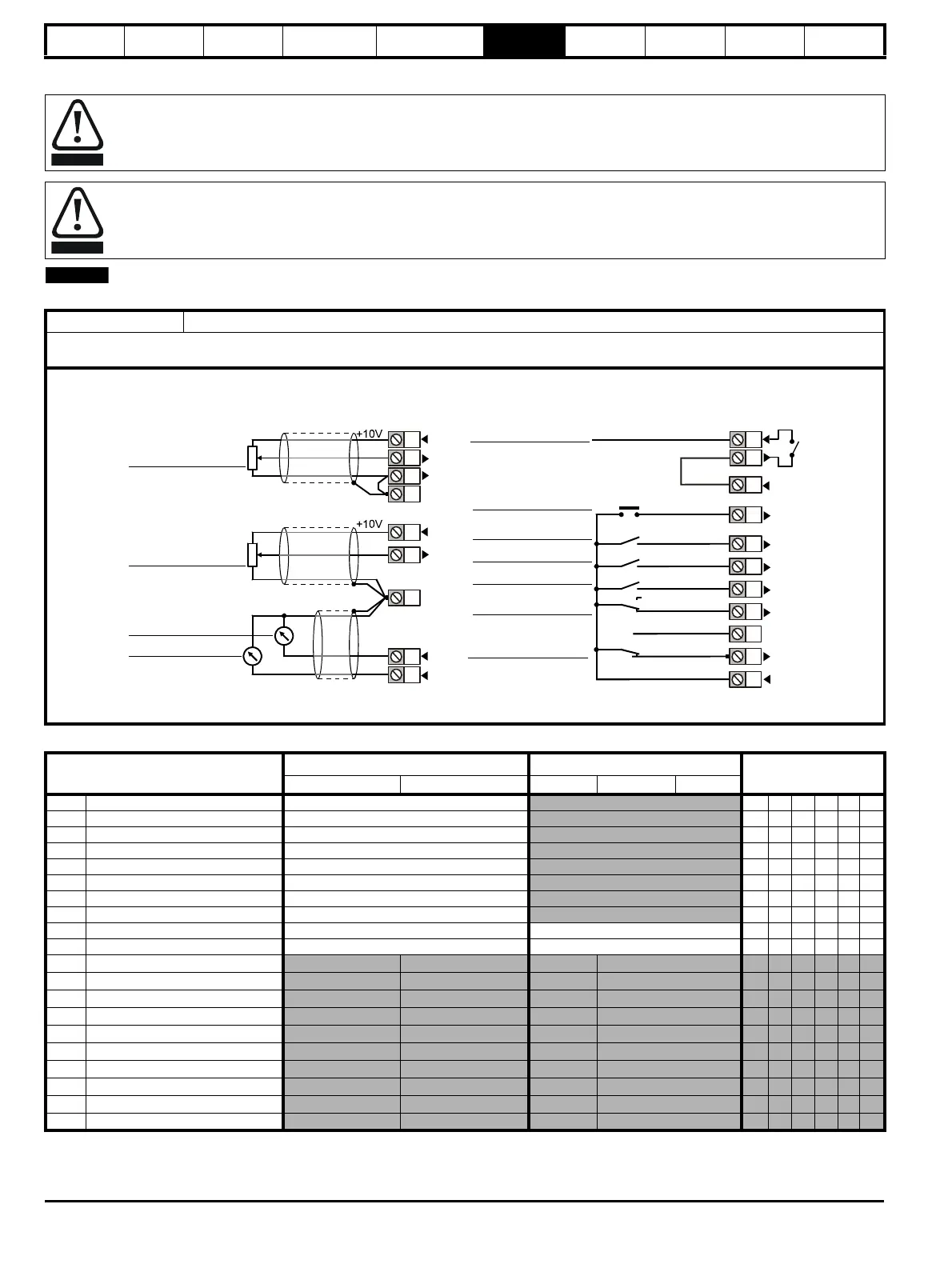
0V common
Analog
frequency/speed
reference 1
0 ~ 10V
SPEED
TORQUE
0V common
CL> JOG
RUN FORWARD
ANALOG INPUT 2
ANALOG INPUT 1
REVERSE
ANALOG INPUT 1 /
INPUT 2
Signal
connector
Analog
frequency/speed
reference 2
0 ~ 10V
25
24
29
26
DRIVE ENABLE
Analog I/O Digital I/O

 Loading...


