Parameter
structure
Keypad and
display
Parameter
x.00
Parameter
description format
Advanced parameter
descriptions
Macros
Serial comms
protocol
Electronic
nameplate
Performance RFC mode
Menu 4
Unidrive SP Advanced User Guide 101
Issue Number: 10 www.controltechniques.com
Closed loop vector and Servo
When this parameter is set to 1, 2 or 3 the ramps are not active while the drive is in the run state. When the drive is taken out of the run state, but not
disabled, the appropriate stopping mode is used. It is recommended that coast stopping or stopping without ramps are used. However, if ramp stop
mode is used the ramp output is pre-loaded with the actual speed at the changeover point to avoid unwanted jumps in the speed reference.
0: Speed control mode
The torque demand is equal to the speed loop output.
1: Torque control
The torque demand is given by the sum of the torque reference and the torque offset, if enabled. The speed is not limited in any way, however, the
drive will trip at the overspeed threshold if runaway occurs.
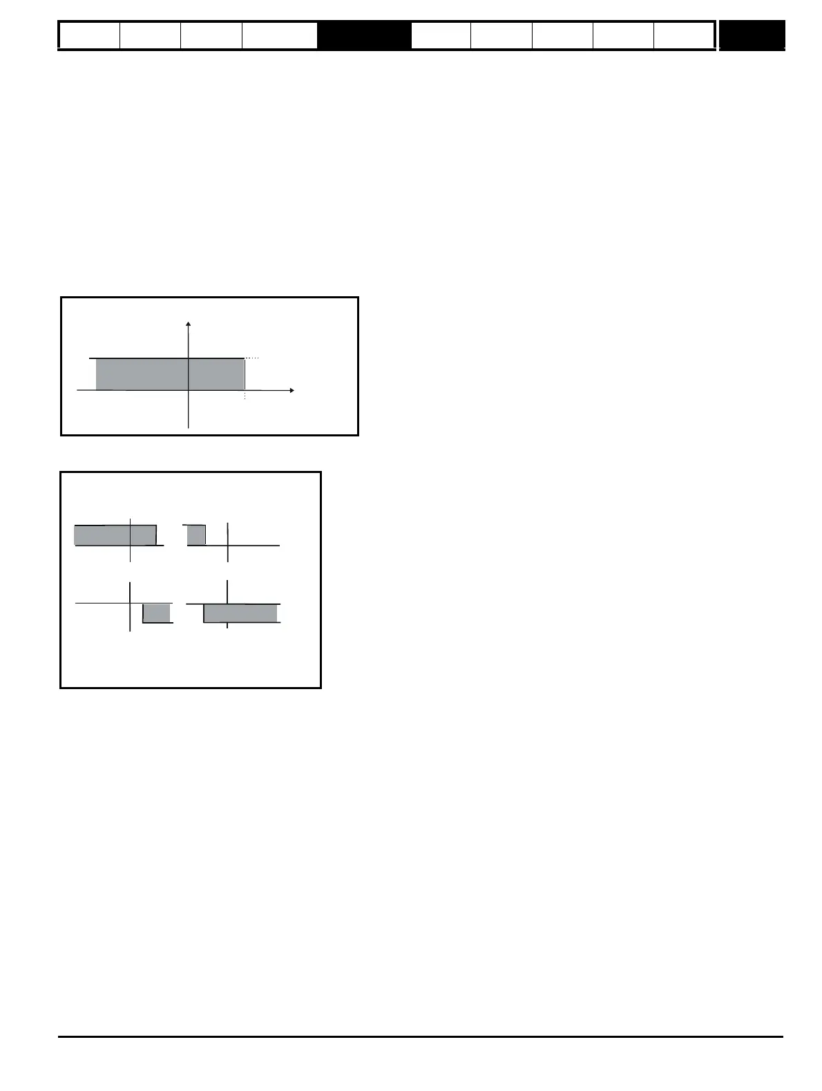
2: Torque control with speed override
The output of the speed loop defines the torque demand, but is limited between 0 and the resultant torque reference (Pr 4.08 + Pr 4.09 (if
enabled)). The effect is to produce an operating area as shown below if the final speed demand and the resultant torque reference are both
positive. The speed controller will try and accelerate the machine to the final speed demand level with a torque demand defined by the resultant
torque reference. However, the speed cannot exceed the reference because the required torque would be negative, and so it would be clamped
to zero.
Depending on the sign of the final speed demand and the resultant torque the four areas of operation shown below are possible.
This mode of operation can be used where torque control is required, but the maximum speed must be limited by the drive.
3: Coiler/uncoiler mode
Positive final speed demand: a positive resultant torque will give torque control with a positive speed limit defined by the final speed demand. A
negative resultant torque will give torque control with a negative speed limit of -5rpm.
Negative final speed demand: a negative resultant torque will give torque control with a negative speed limit defined by the final speed demand. A
positive resultant torque will give torque control with a positive speed limit of +5rpm.
Example of coiler operation:
This is an example of a coiler operating in the positive direction. The final speed demand is set to a positive value just above the coiler reference
speed. If the resultant torque demand is positive the coiler operates with a limited speed, so that if the material breaks the speed does not exceed a
level just above the reference. It is also possible to decelerate the coiler with a negative resultant torque demand. The coiler will decelerate down to -
5rpm until a stop is applied.
Pr +
4.08
Pr (if enabled)
4.09
Pr
3.01
Speed
Current
+ final speed demand
+ resultant torque
- final speed demand
+ resultant torque
+ final speed demand
-resultant torque
- final speed demand
- resultant torque

 Loading...


