Parameter
structure
Keypad and
display
Parameter
x.00
Parameter
description format
Advanced parameter
descriptions
Macros
Serial comms
protocol
Electronic
nameplate
Performance RFC mode
Menu 3
Open-loop
Unidrive SP Advanced User Guide 53
Issue Number: 10 www.controltechniques.com
The slave frequency demand is only relevant if the drive is operating in frequency slaving mode, in other modes this parameter reads as 0.0. The
value shown in slaving mode is the fundamental drive output frequency. Frequency slaving mode is used to lock the fundamental frequency produced
by the drive with an external frequency applied to the main drive encoder input. This could be used for example to keep the shafts of two synchronous
machines in lock, by feeding the frequency slaving output from the master drive into the encoder input of the slave drive. Alternatively the two
machines could be operated so that the shafts rotate with an exact ratio, i.e. as though the shafts were connected by gears (see Pr 3.14 and Pr 3.15
on page 54).
The source for frequency slaving mode may be quadrature A/B encoder signals or Frequency and Direction. With the latter care must be taken to
ensure that the D set-up time (10μs) is observed or pulses may be lost. The frequency slaving input must be selected as F and D or quadrature to
match the source mode. The input mode is selected by Pr 3.38 which defines the encoder type. The default for source and destination drives is
quadrature A/B mode, unlike previous products which used F and D only.
The drive will not count pulses while it is disabled (this parameter will show 0.0), but will maintain lock once enabled even if the direction of rotation
reverses. In frequency slaving mode the drive current limits are not active, however, the drive peak limit is active and will try and limit the drive current
to the magnitude limit by modifying the output voltage away from the defined V to F (Voltage to Frequency) characteristic. If synchronous machines
are used and the current required exceeds the drive magnitude limit the slave machine will pole slip.
If the post ramp reference (Pr 2.01) is at or below the level defined by this parameter in either direction the Zero speed flag (Pr 10.03) is 1, otherwise
the flag is 0.
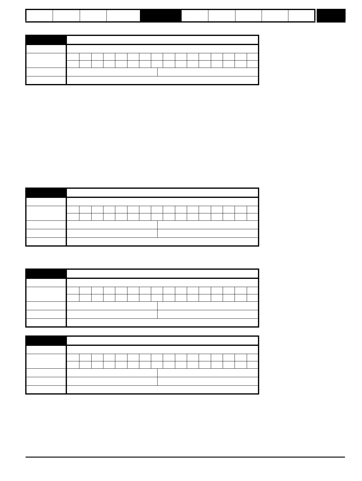
3.01 Frequency slaving demand
Drive modes Open-loop
Coding
Bit SP FI DE Txt VM DP ND RA NC NV PT US RW BU PS
1 1111
Range Open-loop ±1000.0 Hz
Update rate 4ms write
3.05 Zero speed threshold
Drive modes Open-loop, Closed-loop vector, Servo
Coding
Bit SP FI DE Txt VM DP ND RA NC NV PT US RW BU PS
1111
Range Open-loop 0.0 to 20.0 Hz
Default Open-loop 1.0
Update rate Background read
3.06 At speed lower limit
Drive modes Open-loop, Closed-loop vector, Servo
Coding
Bit SP FI DE Txt VM DP ND RA NC NV PT US RW BU PS
1111
Range Open-loop 0.0 to 3,000.0 Hz
Default Open-loop 1.0
Update rate Background read
3.07 At speed upper limit
Drive modes Open-loop, Closed-loop vector, Servo
Coding
Bit SP FI DE Txt VM DP ND RA NC NV PT US RW BU PS
1111
Range Open-loop 0.0 to 3,000.0 Hz
Default Open-loop 1.0
Update rate Background read

 Loading...


